
Associate II
August 23, 2023
Question

UART COM issue with f030r8

  • August 23, 2023
  • 12 replies
  • 7285 views

Hello,

I am trying to use UART HAL with the stm32-f030r8 connected to the PC through a USB-TTL module.

The configuration is given below :
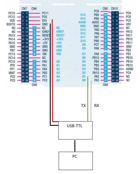
wire.PNG

- The F030R8 has JP1 OFF, JP6 ON, JP5 on E5V.

- The USB-TTL is :
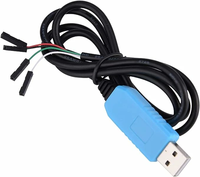
usb-ttl.jpg

- The code is :

/* Includes ------------------------------------------------------------------*/
#include "main.h"

uint8_t test[] = "hello";
UART_HandleTypeDef huart2;

int main(void)
{

HAL_Init();

SystemClock_Config();

__USART2_CLK_ENABLE();
__GPIOA_CLK_ENABLE();

GPIO_InitTypeDef GPIO_InitStructure;

GPIO_InitStructure.Pin = GPIO_PIN_2;
GPIO_InitStructure.Mode = GPIO_MODE_AF_PP;
GPIO_InitStructure.Alternate = GPIO_AF1_USART2;
GPIO_InitStructure.Speed = GPIO_SPEED_HIGH;
GPIO_InitStructure.Pull = GPIO_NOPULL;
HAL_GPIO_Init(GPIOA, &GPIO_InitStructure);

GPIO_InitStructure.Pin = GPIO_PIN_3;
GPIO_InitStructure.Mode = GPIO_MODE_AF_OD;
HAL_GPIO_Init(GPIOA, &GPIO_InitStructure);

huart2.Instance = USART2;
huart2.Init.BaudRate = 9600;
huart2.Init.WordLength = UART_WORDLENGTH_8B;
huart2.Init.Parity = UART_PARITY_NONE ;
huart2.Init.Mode = UART_MODE_TX_RX;
huart2.Init.HwFlowCtl = UART_HWCONTROL_NONE;
huart2.Init.StopBits = UART_STOPBITS_1;

while (1){
HAL_UART_Transmit(&huart2,test,sizeof(test),HAL_MAX_DELAY);
HAL_Delay(1000);
}

}


Then, the putty configuration is 9600 baud, 8 data bits, 1 stop bits, no parity; no flow control.

But I can't see anything in the terminal...

Would you please have suggestions ?


Thanks for your help ! :)

This topic has been closed for replies.

12 replies

ONadr.1
Senior III
August 23, 2023

t is not clear from the schematic if the Rx and Tx labels are for the module or for connecting to an external UART. Maybe the signals are mixed up. But the second problem is the signal level. TTL is for 5V logic, but the MCU uses 3.3V logic. If the MCU pins are not 5V tolerant, the MCU can also be destroyed. I would recommend using a TTL-3.3V level converter.

ST Technical Moderator
August 23, 2023

Hello @ONadr.1 ,

you can refer to the user manual UM1724 Rev 14 Table 11. ARDUINO® connectors on NUCLEO-F030R8, NUCLEO-F070RB, It is mentioned USART2_TX and USART2_RX are linked to PA2 and PA3 respectively. USART2 by default is used for STLINK module.

To give better visibility on the answered topics, please click on "Best answer" on the reply which solved your issue or answered your question.Best regards,FBL
user-stmAuthor
Associate II
August 23, 2023

The Rx and Tx labels are for the wire of the USB-TTL converter : Tx for the green one connected to PA2, Rx for the white one connected to PA3.

ST Technical Moderator
August 23, 2023

Hello @user-stm,

You may need to check the schematic of the board 

MB1136-DEFAULT-C05 Board schematic
 
FBelaid_0-1692786536464.png

As you can see, some changes are needed to work with USART2. Otherwise, you can simply try different USART instance.

Hope this helps!

To give better visibility on the answered topics, please click on "Best answer" on the reply which solved your issue or answered your question.Best regards,FBL
user-stmAuthor
Associate II
August 23, 2023

@FBL 

As a beginner not really familiar with it, would you please detail needed changes ? Thanks !

ST Technical Moderator
August 23, 2023

Hi again @user-stm,

you can disconnect SB13, SB14 and use CN3 to drive TX and RX pins of USART2.

To give better visibility on the answered topics, please click on "Best answer" on the reply which solved your issue or answered your question.Best regards,FBL
user-stmAuthor
Associate II
August 24, 2023

Another question then :

As it is mentioned that "By default, the USART2 communication between the target STM32 and ST-LINK MCU is enabled", if we forget the USB-TTL module ie we have a unique wire (USB Type-A to Mini-B cable) between the PC and the stm32, do you know why is still have anything on putty ?

Configuration with JP1 OFF, JP6 ON and JP5 on U5V and the following code :


/* Includes ------------------------------------------------------------------*/
#include "main.h"


UART_HandleTypeDef huart2;
uint8_t test[] = "hello";


void SystemClock_Config2(void);
static void MX_GPIO_Init(void);
static void MX_USART2_UART_Init(void);
 
 
int main(void)
{
 
  HAL_Init();
 
  SystemClock_Config();
 
  MX_GPIO_Init();
  MX_USART2_UART_Init();
 
  while (1)
  {
 
HAL_UART_Transmit(&huart2,test,sizeof(test),HAL_MAX_DELAY);
HAL_Delay(2000);
 
  }
}


void SystemClock_Config(void)
{
  RCC_OscInitTypeDef RCC_OscInitStruct = {0};
  RCC_ClkInitTypeDef RCC_ClkInitStruct = {0};
 
  RCC_OscInitStruct.OscillatorType = RCC_OSCILLATORTYPE_HSI;
  RCC_OscInitStruct.HSIState = RCC_HSI_ON;
  RCC_OscInitStruct.HSICalibrationValue = RCC_HSICALIBRATION_DEFAULT;
  RCC_OscInitStruct.PLL.PLLState = RCC_PLL_NONE;
  if (HAL_RCC_OscConfig(&RCC_OscInitStruct) != HAL_OK)
  {
    Error_Handler();
  }
 
  RCC_ClkInitStruct.ClockType = RCC_CLOCKTYPE_HCLK|RCC_CLOCKTYPE_SYSCLK
                              |RCC_CLOCKTYPE_PCLK1;
  RCC_ClkInitStruct.SYSCLKSource = RCC_SYSCLKSOURCE_HSI;
  RCC_ClkInitStruct.AHBCLKDivider = RCC_SYSCLK_DIV1;
  RCC_ClkInitStruct.APB1CLKDivider = RCC_HCLK_DIV1;
 
  if (HAL_RCC_ClockConfig(&RCC_ClkInitStruct, FLASH_LATENCY_0) != HAL_OK)
  {
    Error_Handler();
  }
}


static void MX_USART2_UART_Init(void)
{
  huart2.Instance = USART2;
  huart2.Init.BaudRate = 9600;
  huart2.Init.WordLength = UART_WORDLENGTH_8B;
  huart2.Init.StopBits = UART_STOPBITS_1;
  huart2.Init.Parity = UART_PARITY_NONE;
  huart2.Init.Mode = UART_MODE_TX_RX;
  huart2.Init.HwFlowCtl = UART_HWCONTROL_NONE;
  huart2.Init.OverSampling = UART_OVERSAMPLING_16;
  huart2.Init.OneBitSampling = UART_ONE_BIT_SAMPLE_DISABLE;
  huart2.AdvancedInit.AdvFeatureInit = UART_ADVFEATURE_NO_INIT;
  if (HAL_UART_Init(&huart2) != HAL_OK)
  {
    Error_Handler();
  }
}
 
 
static void MX_GPIO_Init(void)
{
  __HAL_RCC_GPIOA_CLK_ENABLE();
}
 
void Error_Handler(void)
{
  __disable_irq();
  while (1)
  {
  }
}


Pavel A.
August 24, 2023

Remove the 5V wire between the dongle and the board. The dongle receives its power from USB.

user-stmAuthor
Associate II
August 24, 2023

If you refer to my last post, there is only one cable (USB Type-A to Mini-B cable) between the PC and the stm32, no USB-TTL module and JP5 on U5V.

In the configuration presented in the first post, there is no USB Type-A to Mini-B cable, only one USB-TTL module (with 5v, GND, tx,rx wires) between the board and the PC, and JP5 on E5V.

Pavel A.
August 24, 2023

Disconnect the 5v wire (RED)  from the TTL module.

user-stmAuthor
Associate II
August 24, 2023

My last question refers to the configuration without TTL module. I put it below again :


As it is mentioned that "By default, the USART2 communication between the target STM32 and ST-LINK MCU is enabled", if we forget the USB-TTL module ie we have a unique wire (USB Type-A to Mini-B cable) between the PC and the stm32, do you know why is still have anything on putty ?

Configuration with JP1 OFF, JP6 ON and JP5 on U5V and the following code :


/* Includes ------------------------------------------------------------------*/
#include "main.h"


UART_HandleTypeDef huart2;
uint8_t test[] = "hello";


void SystemClock_Config2(void);
static void MX_GPIO_Init(void);
static void MX_USART2_UART_Init(void);
 
 
int main(void)
{
 
  HAL_Init();
 
  SystemClock_Config();
 
  MX_GPIO_Init();
  MX_USART2_UART_Init();
 
  while (1)
  {
 
HAL_UART_Transmit(&huart2,test,sizeof(test),HAL_MAX_DELAY);
HAL_Delay(2000);
 
  }
}


void SystemClock_Config(void)
{
  RCC_OscInitTypeDef RCC_OscInitStruct = {0};
  RCC_ClkInitTypeDef RCC_ClkInitStruct = {0};
 
  RCC_OscInitStruct.OscillatorType = RCC_OSCILLATORTYPE_HSI;
  RCC_OscInitStruct.HSIState = RCC_HSI_ON;
  RCC_OscInitStruct.HSICalibrationValue = RCC_HSICALIBRATION_DEFAULT;
  RCC_OscInitStruct.PLL.PLLState = RCC_PLL_NONE;
  if (HAL_RCC_OscConfig(&RCC_OscInitStruct) != HAL_OK)
  {
    Error_Handler();
  }
 
  RCC_ClkInitStruct.ClockType = RCC_CLOCKTYPE_HCLK|RCC_CLOCKTYPE_SYSCLK
                              |RCC_CLOCKTYPE_PCLK1;
  RCC_ClkInitStruct.SYSCLKSource = RCC_SYSCLKSOURCE_HSI;
  RCC_ClkInitStruct.AHBCLKDivider = RCC_SYSCLK_DIV1;
  RCC_ClkInitStruct.APB1CLKDivider = RCC_HCLK_DIV1;
 
  if (HAL_RCC_ClockConfig(&RCC_ClkInitStruct, FLASH_LATENCY_0) != HAL_OK)
  {
    Error_Handler();
  }
}


static void MX_USART2_UART_Init(void)
{
  huart2.Instance = USART2;
  huart2.Init.BaudRate = 9600;
  huart2.Init.WordLength = UART_WORDLENGTH_8B;
  huart2.Init.StopBits = UART_STOPBITS_1;
  huart2.Init.Parity = UART_PARITY_NONE;
  huart2.Init.Mode = UART_MODE_TX_RX;
  huart2.Init.HwFlowCtl = UART_HWCONTROL_NONE;
  huart2.Init.OverSampling = UART_OVERSAMPLING_16;
  huart2.Init.OneBitSampling = UART_ONE_BIT_SAMPLE_DISABLE;
  huart2.AdvancedInit.AdvFeatureInit = UART_ADVFEATURE_NO_INIT;
  if (HAL_UART_Init(&huart2) != HAL_OK)
  {
    Error_Handler();
  }
}
 
 
static void MX_GPIO_Init(void)
{
  __HAL_RCC_GPIOA_CLK_ENABLE();
}
 
void Error_Handler(void)
{
  __disable_irq();
  while (1)
  {
  }
}


waclawek.jan
Super User
August 24, 2023

On Nucleo (and Disco/EVAL), always start with reading the manual and looking at schematics for jumpers/solder bridges (SBxx) settings.

waclawekjan_0-1692874644017.png

But maybe instead of changing the SB settings, you might want to leave them for the PA2/PA3 being used through the on-board STLink's VCP; and if you want for some reason to use the additional external USB-UART connection, use different pins/UART.

Also, as others said, you have to cross-connect the cable, Rx to Tx and vice versa (unless the USB-UART converter's author mislabelled the wires).

JW