

Solved
Typo inside the STM32F429 datasheet?
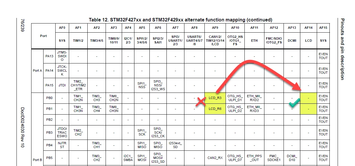
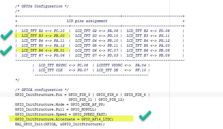
Hi. Believe to have found a typo inside the STM32F429 datasheet (document DocID024030 Rev 10). Studying the use of the STM32F429NI DISC1 Kit and the use of the onboard TFT display. The source code is noting that the CPU is configured into AF14 (alternate function 14) which sounds correct. Yet the RGB pins are not correctly mapped under AF14 inside the datasheet.
Specifically, Table 12 is showing that:
PB0 = LCD_R3 (if using AF9) but should be PB0 = LCD_R3 (if using AF14)
PB1 = LCD_R6 (if using AF9) but should be PB1 = LCD_R6 (if using AF14)
The IAR source code mapping looks to be correct as it is working:
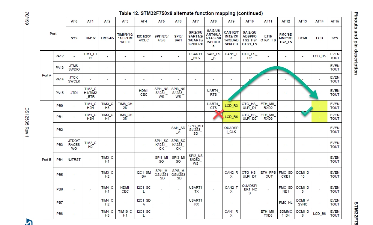
and same typo in the STM32F750x8 datasheet?
Please correct if my error.
Thanks.
