

Associate II
Nov 18, 2026 4:25 PM UTC
Question

Timer source on the STM32N6?

I’ve setup a PWM timer on the STM32N6:
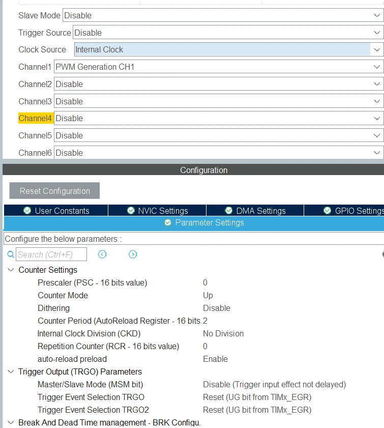
 

Using the above settings, checking with a scope shows an output of about 22MHz, suggesting a clock source of something around 60MHz.  I do not see this on the clock tree:
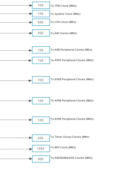
This is closer:
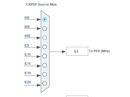
When using the internal clock source, what is the source of the timer clock?  Or, is there another divider that I am not aware of?


4 replies

AScha.3
Super User
Nov 18, 2026 5:30 PM UTC

>a PWM timer

Fine. out of 14 timers…

probably : timer group

> on the STM32N6

same...out of 24 possible types.

+

whats PLL/master clock source ?


Or is it on a Nucleo board ?

+

check this:  -- maybe generated code set wrong calculation ?


+

check by using MCO output the internal clks , you really run, with a scope.


If you feel a post has answered your question, please click on " Best Answer ".
TDK
Nov 18, 2026 5:53 PM UTC

Timer source on the STM32N6?

The clock source for the timers is the “Timer Group Clocks” in the screenshot--400 MHz.


For the logical next question, you should provide more information on how your timer and clock source are set up. Could be any number of things wrong. Possibly wrong HSE value, or using a prescaler.

ARR of 2 means the period is 3x the tick rate, not 2x. In which case your wave will be asymmetric, unless you have it set up to toggle. Maybe show what you measured--sample rate could be insufficient. Maybe set up the prescaler to measure something slower, like a 1 MHz wave.

"If you feel a post has answered your question, please click ""Accept as Solution""."
Associate II
Nov 18, 2026 6:20 PM UTC

Here is the actual timer setup code:

static void MX_TIM1_Init(void)
{

  /* USER CODE BEGIN TIM1_Init 0 */

  /* USER CODE END TIM1_Init 0 */

  TIM_ClockConfigTypeDef sClockSourceConfig = {0};
  TIM_MasterConfigTypeDef sMasterConfig = {0};
  TIM_OC_InitTypeDef sConfigOC = {0};
  TIM_BreakDeadTimeConfigTypeDef sBreakDeadTimeConfig = {0};

  /* USER CODE BEGIN TIM1_Init 1 */

  /* USER CODE END TIM1_Init 1 */
  htim1.Instance = TIM1;
  htim1.Init.Prescaler = 0;
  htim1.Init.CounterMode = TIM_COUNTERMODE_UP;
  htim1.Init.Period = 2;
  htim1.Init.ClockDivision = TIM_CLOCKDIVISION_DIV1;
  htim1.Init.RepetitionCounter = 0;
  htim1.Init.AutoReloadPreload = TIM_AUTORELOAD_PRELOAD_ENABLE;
  if (HAL_TIM_Base_Init(&htim1) != HAL_OK)
  {
    Error_Handler();
  }
  sClockSourceConfig.ClockSource = TIM_CLOCKSOURCE_INTERNAL;
  if (HAL_TIM_ConfigClockSource(&htim1, &sClockSourceConfig) != HAL_OK)
  {
    Error_Handler();
  }
  if (HAL_TIM_PWM_Init(&htim1) != HAL_OK)
  {
    Error_Handler();
  }
  sMasterConfig.MasterOutputTrigger = TIM_TRGO_RESET;
  sMasterConfig.MasterOutputTrigger2 = TIM_TRGO2_RESET;
  sMasterConfig.MasterSlaveMode = TIM_MASTERSLAVEMODE_DISABLE;
  if (HAL_TIMEx_MasterConfigSynchronization(&htim1, &sMasterConfig) != HAL_OK)
  {
    Error_Handler();
  }
  sConfigOC.OCMode = TIM_OCMODE_PWM1;
  sConfigOC.Pulse = 1;
  sConfigOC.OCPolarity = TIM_OCPOLARITY_HIGH;
  sConfigOC.OCNPolarity = TIM_OCNPOLARITY_HIGH;
  sConfigOC.OCFastMode = TIM_OCFAST_DISABLE;
  sConfigOC.OCIdleState = TIM_OCIDLESTATE_RESET;
  sConfigOC.OCNIdleState = TIM_OCNIDLESTATE_RESET;
  if (HAL_TIM_PWM_ConfigChannel(&htim1, &sConfigOC, TIM_CHANNEL_1) != HAL_OK)
  {
    Error_Handler();
  }
  sBreakDeadTimeConfig.OffStateRunMode = TIM_OSSR_DISABLE;
  sBreakDeadTimeConfig.OffStateIDLEMode = TIM_OSSI_DISABLE;
  sBreakDeadTimeConfig.LockLevel = TIM_LOCKLEVEL_OFF;
  sBreakDeadTimeConfig.DeadTime = 0;
  sBreakDeadTimeConfig.BreakState = TIM_BREAK_DISABLE;
  sBreakDeadTimeConfig.BreakPolarity = TIM_BREAKPOLARITY_HIGH;
  sBreakDeadTimeConfig.BreakFilter = 0;
  sBreakDeadTimeConfig.BreakAFMode = TIM_BREAK_AFMODE_INPUT;
  sBreakDeadTimeConfig.Break2State = TIM_BREAK2_DISABLE;
  sBreakDeadTimeConfig.Break2Polarity = TIM_BREAK2POLARITY_HIGH;
  sBreakDeadTimeConfig.Break2Filter = 0;
  sBreakDeadTimeConfig.Break2AFMode = TIM_BREAK_AFMODE_INPUT;
  sBreakDeadTimeConfig.AutomaticOutput = TIM_AUTOMATICOUTPUT_DISABLE;
  if (HAL_TIMEx_ConfigBreakDeadTime(&htim1, &sBreakDeadTimeConfig) != HAL_OK)
  {
    Error_Handler();
  }
  /* USER CODE BEGIN TIM1_Init 2 */

  /* USER CODE END TIM1_Init 2 */
  HAL_TIM_MspPostInit(&htim1);

}
 

I measured the PWM signal period on the scope and as I said, I’m getting about 22MHz.  The duty cycle is about 50%.

TDK
Nov 18, 2026 6:27 PM UTC

The duty cycle in the setup code you posted is 33%/66%, not 50%. Something else is going on. Possibly other code is changing it, or the code you think is running is not running. Or you’re not measuring what you think you’re measuring.

"If you feel a post has answered your question, please click ""Accept as Solution""."