

Associate II
July 27, 2026
Question

STM32U545 ADC Non-linear Problem

  • July 27, 2026
  • 13 replies
  • 200 views

Hi ST,

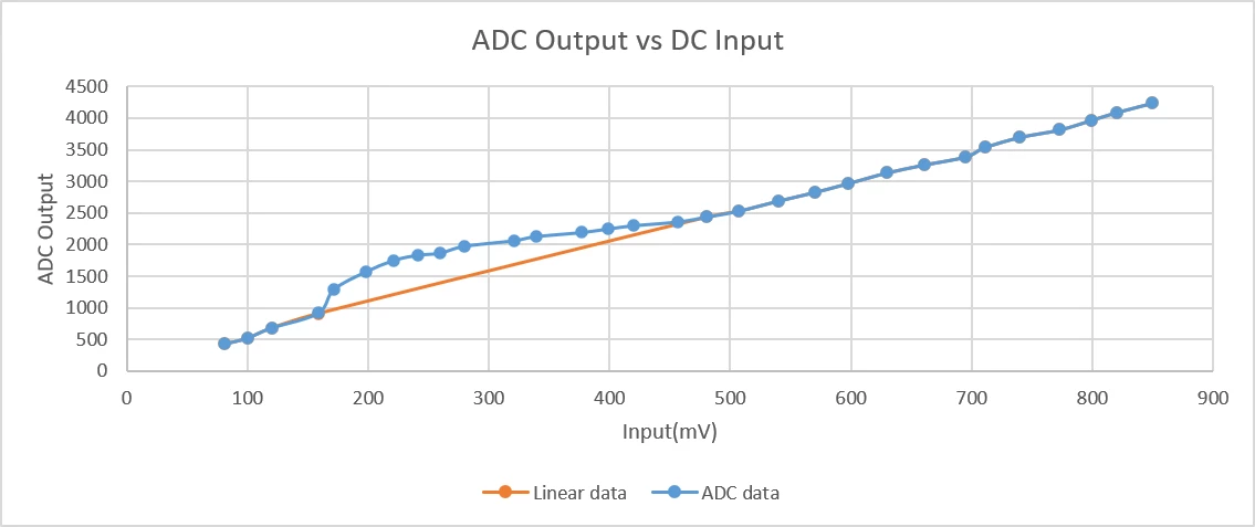
I found a problem of fixed-range local ADC non-linearity from 170mV to 480mV on STM32U545 after full hardware linear calibration.

1. Test Environment

HW: NUCLEO-U545RE-Q board (MB1841D), 

Firmware package: STM32CubeU5 FW V1.8.0.

Test instruments: Precision DC power supply, function signal generator, digital oscilloscope (used to verify the actual voltage at ADC input pins).

Working Mode: Button→ LPTimer→ ADC→ DMA→ UART

MX: See attachment

Main code: See attachment

2. Two types of input tests (static DC + dynamic triangle wave, identical distortion observed)

(1) Static DC step voltage test

We applied stepped DC voltage from 81mV to 850mV via precision power supply and resistor voltage divider. The real voltage on ADC1 input pins was measured and recorded with an oscilloscope for every step, ruling out inaccuracies from signal sources or resistor division. Test results: ADC1 conversion curve is perfectly linear below 170mV and above 480mV. A consistent concave distortion only exists within 170mV ~ 480mV. This error occurs on both ADC1 and ADC4 (maybe not same error range in ADC4), under single-ended and differential input modes.
(2) Dynamic triangle wave test

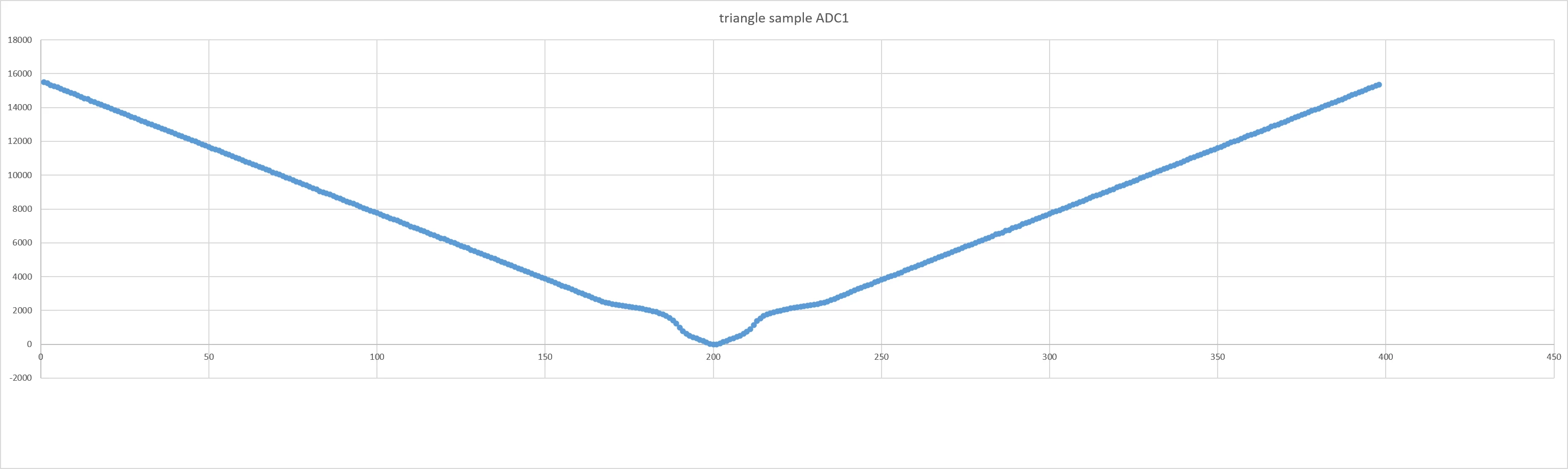
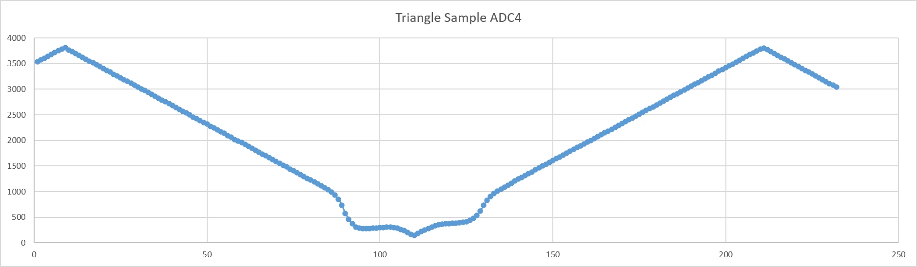
Slow triangle wave generated by function generator was fed into ADC for continuous sampling. In ADC1, The same concave distortion appears whenever the waveform sweeps across 170mV~480mV. The shape and position of non-linearity are exactly the same as DC measurement results. This confirms the error originates from the ADC internal core itself, not input signal dynamic characteristics. for ADC4, there is still a non-linear with different shape.
3. Interference factors all verified and excluded

  1. I used HAL_ADCEx_Calibration_Start(&hADC, ADC_CALIB_OFFSET_LINEARITY, ADC_SINGLE_ENDED); to calibrate, but with no effect.
  2. ADC sampling time was adjusted from 5 cycles up to 36 cycles; no change to the non-linear curve.
  3. We tested with only ADC1 enabled (ADC4 clock and peripherals fully disabled), so crosstalk between two ADC modules is not the root cause.
  4. Control test on STM32H750 with identical circuit and ADC configuration, delivers excellent linearity across the full 0~3.3V range without such local distortion.

13 replies

unsigned_char_array
Lead III
July 27, 2026

What is the output impedance of the voltage divider?
Using a buffer or at least a capacitor on the output helps lower the output impedance. 
This might solve some non-linearity.

"Kudo posts if you have the same problem and kudo replies if the solution works.Click ""Accept as Solution"" if a reply solved your problem. If no solution was posted please answer with your own."
Associate II
July 28, 2026

The real voltage on ADC1 input pins was measured and recorded with an oscilloscope for every step

Though the input is divided by resistor, but the input I record is measured from ADC pin by oscilloscope, and the input is DC. Dose the output impedance still matter?

MasterT
Lead II
July 28, 2026

Impedance is very important, since SAR ADC is switching capacitor load. Doesn’t matter if DC or AC, internal sample and hold capacitor generates “spike”, and it’s easy to observe with properly adjusted o-scope. 

 Options: buffering voltage divider by fast OP-AMP, or simply put a capacitor 0.1uF in parallel to inputs - for low sampling rate.

Ozone
Principal
July 27, 2026

Have you tried another Nucleo board ?

Have you tried different sample times ?

Associate II
July 28, 2026

I don’t have another board or another chip. not sure if this is a single problem. Even it is, since it happens this time, will it be a risk?

I have tried different sample time from 5 cycles to 36 cycles, and I think the sample time is not very important in DC input condition. And I also tried different sample rate for triangle signal, I set 100kHz timer to sample 10k signal, 10kHz sample rate for 1k signal, the problem is the same.

AScha.3
Super User
July 28, 2026

So try measurement -as recommended- with an 100 nF cer.cap direct at the ADC input to GND.

And show result , triangle signal.

If you feel a post has answered your question, please click on " Best Answer ".
Associate II
July 29, 2026

 @MasterT ​@unsigned_char_array  ​@Ozone ​@AScha.3 

Hi guys, thank you for your replies. I @ you because I might make wrong conclusion before. I thought it was impedance problem, but it is not. I tried with DC power supply as input directly, no resistor divider this time. but the non-linear still exists.

I also tried to put the integrated OPA of U545 in serial between signal and ADC, it can’t solve the problem either.

For now, I think the impedance is not the key. Only the sampling time higher than 391.5cycles can solve the problem,  68cycles has its effect but not enough. there are no choices between 68 and 391, the sample rate is not enough under 391. this is not suitable for me.

I asked AI, not sure if it is right. it says:

“Low-density STM32U535/U545 integrate a 14-bit segmented SAR ADC with bridge-capacitor CDAC. The capacitor array is divided into separate MSB and LSB sections connected via one bridge capacitor to save silicon area and lower leakage. Layout mismatch of the bridge capacitor plus switch parasitics create local non-linearity, most obvious in the 170 mV ~ 480 mV input range, where both capacitor segments work jointly and charge coupling heavily relies on the bridge capacitor. Since this phenomenon arises inside the ADC, low-impedance drive or input capacitors on the PCB cannot resolve the distortion.

When sampling time is short, residual charge imbalance between internal capacitors cannot settle fully after the sampling switch closes, generating conversion error. If we extend sampling time long enough, complete charge redistribution across all internal nodes is achieved, and the non-linear distortion fades out.”

I cancelled the best answer to make this topic open. I will continue updating it here.

AScha.3
Super User
July 29, 2026

@oldplaychild ,

so this nonlinearity is a defect of the 14-bit converter in U series; could you proof with a simple measurement , with low input impedance or cap o input, on ADC4 (12bit , different architecture) that there is no such problem ?

+

>Layout mismatch of the bridge capacitor plus switch parasitics create local non-linearity, most obvious in the 170 mV ~ 480 mV input range, where both capacitor segments work jointly and charge coupling heavily relies on the bridge capacitor.

<   

Seems the problem should be away or smaller , if ADC clk is slower; so try using a lower clock for the ADC , set prescaler →

and use medium sampling time, try 12 cycles. So effective sample rate is still fast enough.

The nonlinearity should disappear at lower internal ADC clock.

+

So using the differential input mode should improve this, could you try it on ADC1 ?

If you feel a post has answered your question, please click on " Best Answer ".
Associate II
July 30, 2026

On ADC4 there is also this problem with 50ohm signal generator, not sure if it still exists with power supply directly, I will try later.

About the clock, it is a good idea, we may be able to find a balance between clock and sampling time, to achieve best sample rate without nonlinear.

Associate II
July 30, 2026

I replaced the u545 with u585, there is no such problem. 

AI says u585/75 has better architecture than u545/35. Though they have same segmented SAR ADC with bridge-capacitor CDAC, 85/75 will have better performance.

I don’t have another u545 chip so it is not sure if this problem is a single one or it is a problem of u545 series.