

Associate II
August 19, 2026
Question

STM32N657X0H3Q – Low Resistance on VDDCORE Before Power-Up

  • August 19, 2026
  • 4 replies
  • 101 views

Hello ST Community,

We are currently developing a custom board using the STM32N657X0H3Q MCU with the internal SMPS configuration.

We have assembled 5 prototype boards, and before applying power to any of the boards, we measured the resistance between the VDDCORE_0V8 rail and GND.

We observed a relatively low resistance on all 5 boards, with different measured values:

Board    Measurement Point    VDDCORE_0V8 to GND
Board 1    TP16 / TP24    22.32 Ω
Board 2    TP16 / TP24    25.9 Ω
Board 3    TP16 / TP24    20.9 Ω
Board 4    TP16 / TP24    12.8 Ω
Board 5    TP16 / TP24    16.2 Ω

Important: None of the boards have been powered up yet.

The VDDCORE rail is generated using the STM32N657X0H3Q internal SMPS, with an expected VDDCORE voltage of approximately 0.8 V. The VDDCORE pins are connected according to our schematic, and the internal SMPS pins (VDDSMPS, VLXSMPS, VFBSMPS and VSSSMPS) are also connected as shown in the attached schematic.

We are concerned about the low resistance readings, particularly because several boards show approximately 13–26 Ω between VDDCORE and GND.

Could you please advise:

  • Is it normal to measure a resistance in the range of 12–26 Ω between VDDCORE and GND on an unpowered STM32N657X0H3Q?
  • Can the internal circuitry of the STM32N6 cause such a low resistance measurement on the VDDCORE rail?
  • Is there a recommended resistance or diode-mode test procedure for checking VDDCORE before the first power-up?
  • Should we perform any additional checks on the VDDSMPS, VLXSMPS and VFBSMPS pins before powering the board?
  • Is there any risk in powering the board with these measured resistance values?
  • Could the variation between boards (12.8 Ω to 25.9 Ω) be related to normal device-to-device variation, or should we suspect an assembly/PCB issue?

For reference, I have attached the STM32N657X0H3Q power schematic page from our custom board design.
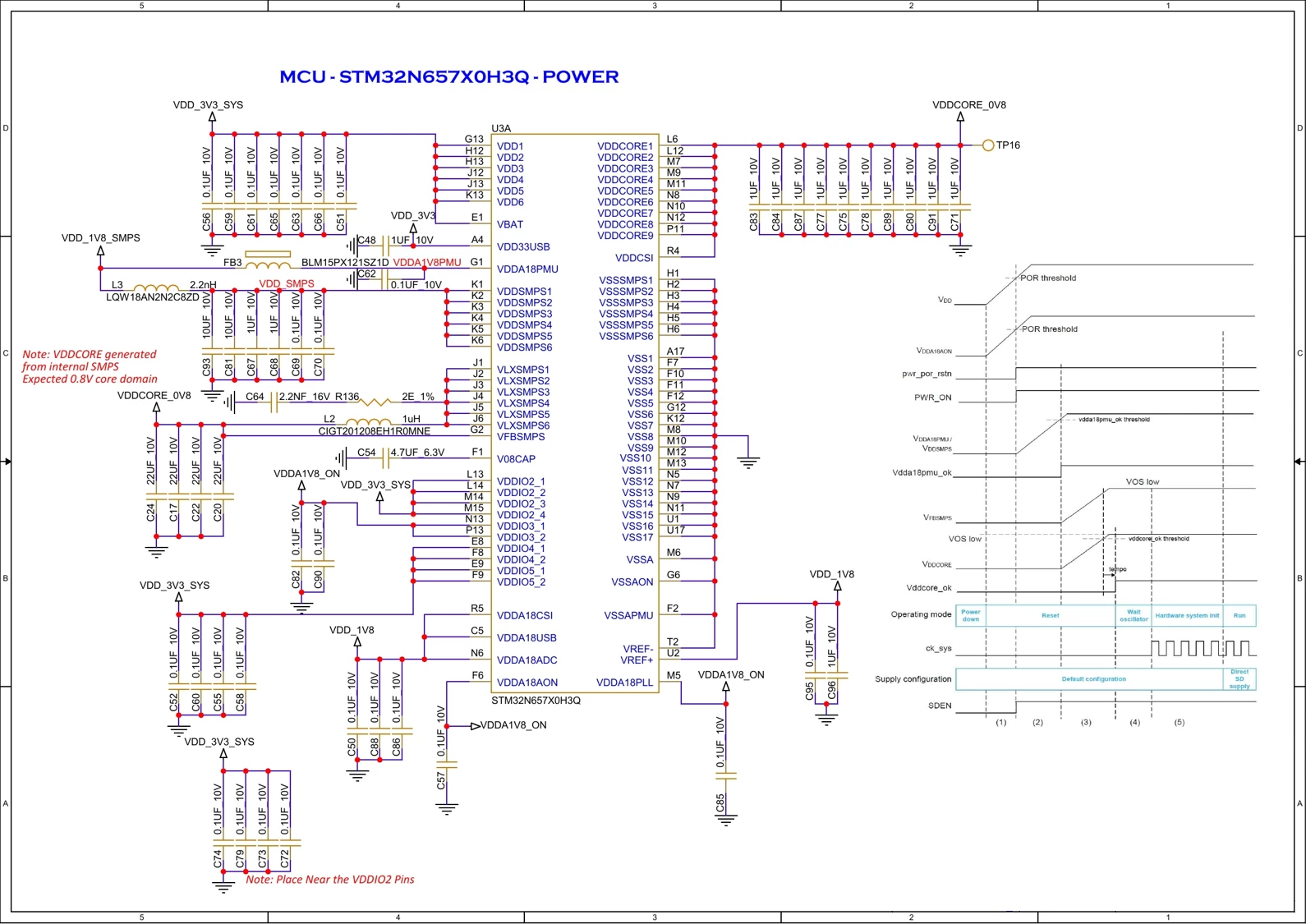
We would appreciate guidance on the recommended checks before applying power to these boards.

Thank you.

4 replies

AScha.3
Super User
August 19, 2026

Hi,

I have no N6 here, but a H7S3 ; i just test it and it shows 8 ...600 ohms, depending on the meter and the polarity.

So your N6 with 20 ohm , would dissipate at 0.8 V core about 40 mA ; 

from ds it could need 200 mA for the core ;  

so maybe ….try another DMM and specify : polarity, applied voltage and current, on the “resistance” measurement.

As there is a complex MOS circuit inside, you only see a “side effect” when simply measuring resistance, as the circuits not really working, you measure a mix of MOSFETS beginning to conduct, depending on the applied voltage, very nonlinear.

So to compare : i measured a defective H7A3 cpu, it showed about 1.6 ohms VDD to GND,

needing > 1,7 A at 3v3 --- so this is obviously dead.  Yours should be ok.

+

Or just power one of the boards, increase voltage slowly and watch the consumed current;

if its in range ( < 200mA ) , it should be ok, then try connect with st-link. 

Just touch it, it should not burn your finger… :)


If you feel a post has answered your question, please click on " Best Answer ".
Richard Li
Senior
August 19, 2026

You can use bench power supply, set current limit to 200mA, if circuit bad, the power supply will drop without damage.

Danish1
Lead III
August 19, 2026

It’s possible resistance isn’t a useful measurement.

How does your meter measure resistance?

The usual technique is to try to drive a certain current between the probes, and measure the voltage. And the current changes depending which resistance range you are on. Of course when auto-ranging the meter will switch currents.

Complications set in where you have non-linear components like diodes present in your circuit. If the resulting voltage is high enough to turn on one of the diodes then you’re not measuring a true resistance, you’re measuring the turn-on-voltage of the diode.

And pretty much every pin on your stm32 has diodes on it for electrostatic protection. One going to Vss and one to an appropriate positive clamp which would be Vdd for pins that are not 5V-compatible, or a special 5V ring for those that are (once Vdd is powered-up).

If your circuit is otherwise unpowered, so Vdd is also at 0V, then the resistance you’re measuring is that of the electrostatic protection diode for the VddCore pin.

There are some multimeters (I have one) that have a “Hi/Lo” switch for the ohms range, and when set to Lo the voltage isn’t allowed to go high enough to turn on diodes. But I think the suggestion by ​@Richard Li of limiting the current to your board and powering up is probably as good as any.

Ajnas-cAuthor
Associate II
August 20, 2026

Thanks, team, for your comments and support. I have powered up the device and confirmed that the internal core output is 0.8 V, which is as expected.

I’m new to this platform, so I raised the query to clarify the observation before powering up the device.