

Kcloc.1
Associate
November 20, 2020
Solved

STM32L476RG Differential ADC functioning as singled-ended

  • November 20, 2020
  • 6 replies
  • 9644 views

I am working on a project using the STM32L476RG microcontroller and have run into an issue with using the ADC in differential configuration. When using the ADC configured as differential the output from the ADC is the same as if it was configured as a single-ended channel, meaning it contains a DC-offset of 1/2 VDD and is 1/2 my expected amplitude. To further explore this I have tested several things:

  1. Scoped the input to both channels of the ADC and can confirm both channels' AFE are operational and sampling noise is present on both channels
  2. Configured the ADC as singled eneded for both the positive and negative channel (ADC1 IN 5 and 6). Both of these outputs are similar to the differential configured version.
  3. Sampled both channels and in software created a pesudo-differential configuation where I subtract channel 6 from channel 5 before logging.
  4. Set the device to debug and checked on in the ADC SFR for the diffsel bit. The bit has been set correctly.

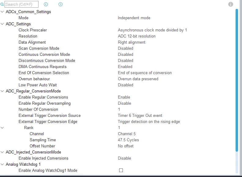
Some background on the steup I am using CubeMX with the latest STM32L4 FW package to generate startup code. The ADC is sampling off of timer 6 at 16khz and running off of an 80MHz clock, I have tried various sample time configurations currenlty using 47.5 cycles. The ADC is running on DMA into a circular buffer. I have tried casting this buffer as both signed and unsigned int16 and neither has changed the outputs. Below is a screen shot of my CubeMxSettings for the ADC.
0693W000005C3QuQAK.png 

For my application I can get away with a pesudo-differntial configuration, but I am wondering if there is somthing I have not setup correctly with the differential ADC inputs.

This topic has been closed for replies.
Best answer by TDK

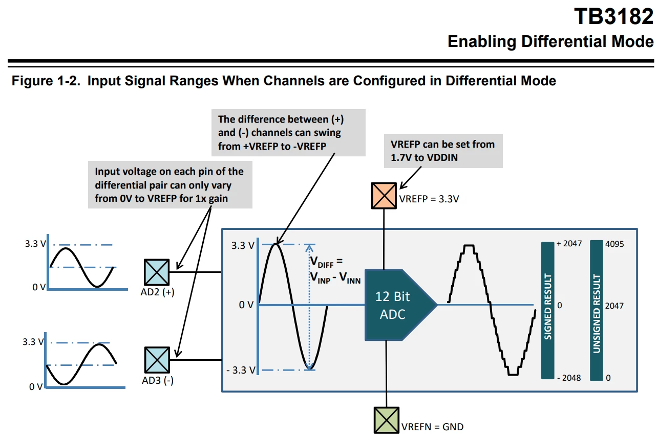
I think the issue is that the output in SE mode should look the same as the output in differential mode, for this particular signal comparison. But you are simple noting that they look the same and therefore it's not working. Hook up VREF- to ground and you'll see a difference.

In differential mode, an output around mid-scale indicates a voltage of 0V, not VDD/2.

Also, as noted above, there is a factor of 2 difference in amplitude in differential mode compared to single-ended.

0693W000005CAiqQAG.png 

Also:

http://ww1.microchip.com/downloads/en/DeviceDoc/90003182A.pdf

6 replies

Ozone
Principal
November 20, 2020

I don't know the L4 series, but none of the STM32 I know support true differential ADC inputs.

"Differential" in the STM32 context usually means "difference between two ADC inputs" instead of ADC input vs. AGND.

To be true differential, a positive and negative VDDA would be required.

Uwe Bonnes
Chief
November 20, 2020

Range is VREF in single- and 2 * VREF in differential mode. If you use differential mode as pseudo-differential ( one input at a fixed voltage), you loose one bit.

TDK
November 20, 2020

> When using the ADC configured as differential the output from the ADC is the same as if it was configured as a single-ended channel, meaning it contains a DC-offset of 1/2 VDD and is 1/2 my expected amplitude.

Not sure if I'm misunderstanding something here, but a DC offset of 1/2 VDD is how it behaves in differential mode, not single-ended mode. What are the actual voltages and raw readings you're getting in both modes?

"If you feel a post has answered your question, please click ""Accept as Solution""."
Kcloc.1
Kcloc.1Author
Associate
November 20, 2020

Here is a plot of the voltages. The input signal is a 500mV pk-pk triangle wave centered around 1.65V, 1/2 VDD, with an inverted copy present on the negative input. When the ADC is configured as differential input it is not showing a subtraction between the two inputs but showing as if it is a single-ended input or subtracting from Vrefn, 0V. I expected an ouptut similar to the PD where the output is the P - N inputs. 0693W000005CAR1QAO.jpg

TDK
TDKBest answer
November 20, 2020

I think the issue is that the output in SE mode should look the same as the output in differential mode, for this particular signal comparison. But you are simple noting that they look the same and therefore it's not working. Hook up VREF- to ground and you'll see a difference.

In differential mode, an output around mid-scale indicates a voltage of 0V, not VDD/2.

Also, as noted above, there is a factor of 2 difference in amplitude in differential mode compared to single-ended.

0693W000005CAiqQAG.png 

Also:

http://ww1.microchip.com/downloads/en/DeviceDoc/90003182A.pdf

"If you feel a post has answered your question, please click ""Accept as Solution""."