

Senior II
Jun 30, 2025 5:53 PM UTC
Question

STM32L433RCT VDDUSB and BOOT0 pin for firmware updates via USB

I am using the NUCLEO-L433RC-P development board and in the process of designing my own PCB.

I would like to be able to update firmware via USB, but need to make sure my PCB design allows for this.

Currently I have VDDUSB connected to 3.3V, but thinking this is now incorrect.

The VDDUSB pin is not rated to 5V, so I can't connect the 5V from the USB-C connector to the VDDUSB pin.

Presumably the VDDUSB is used to indicate to the MCU that the USB cable is connected ?  Is VDDUSB used as a signal or for power ?

Should I just use a linear regulator to convert the USB 5V to 3.3V for the VDDUSB pin ?

Also, the BOOT0 pin has to be pulled high to put the STM32 into bootloader mode.

Can BOOT0 be connected to a pin on the USB-C connector ?

Otherwise I would need an external connector to pull up the BOOT0 pin which does not seem user friendly.
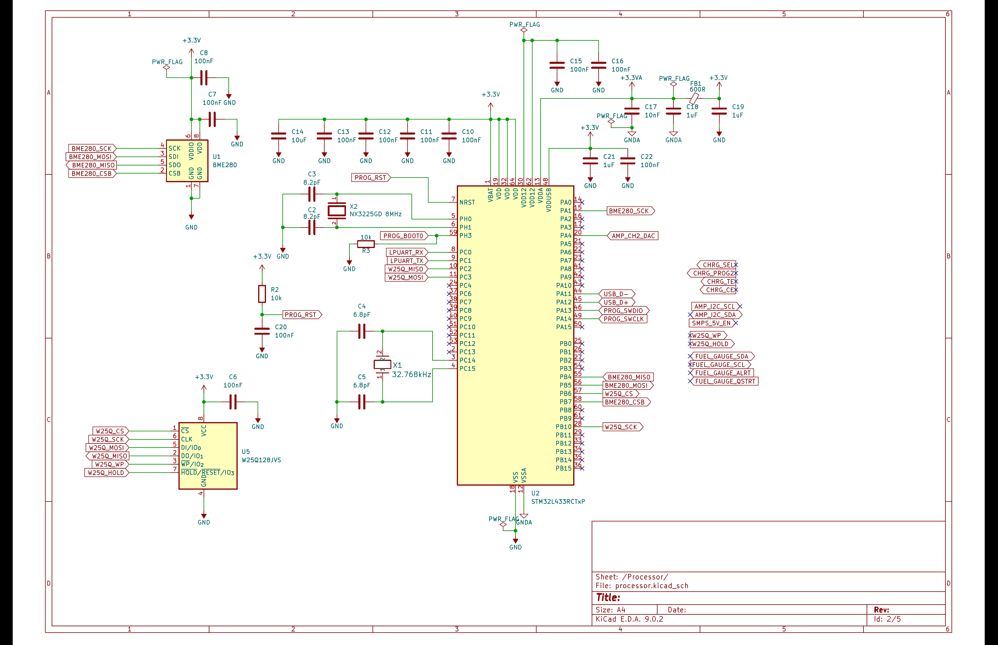
 

freeflyer_0-1751305339478.png

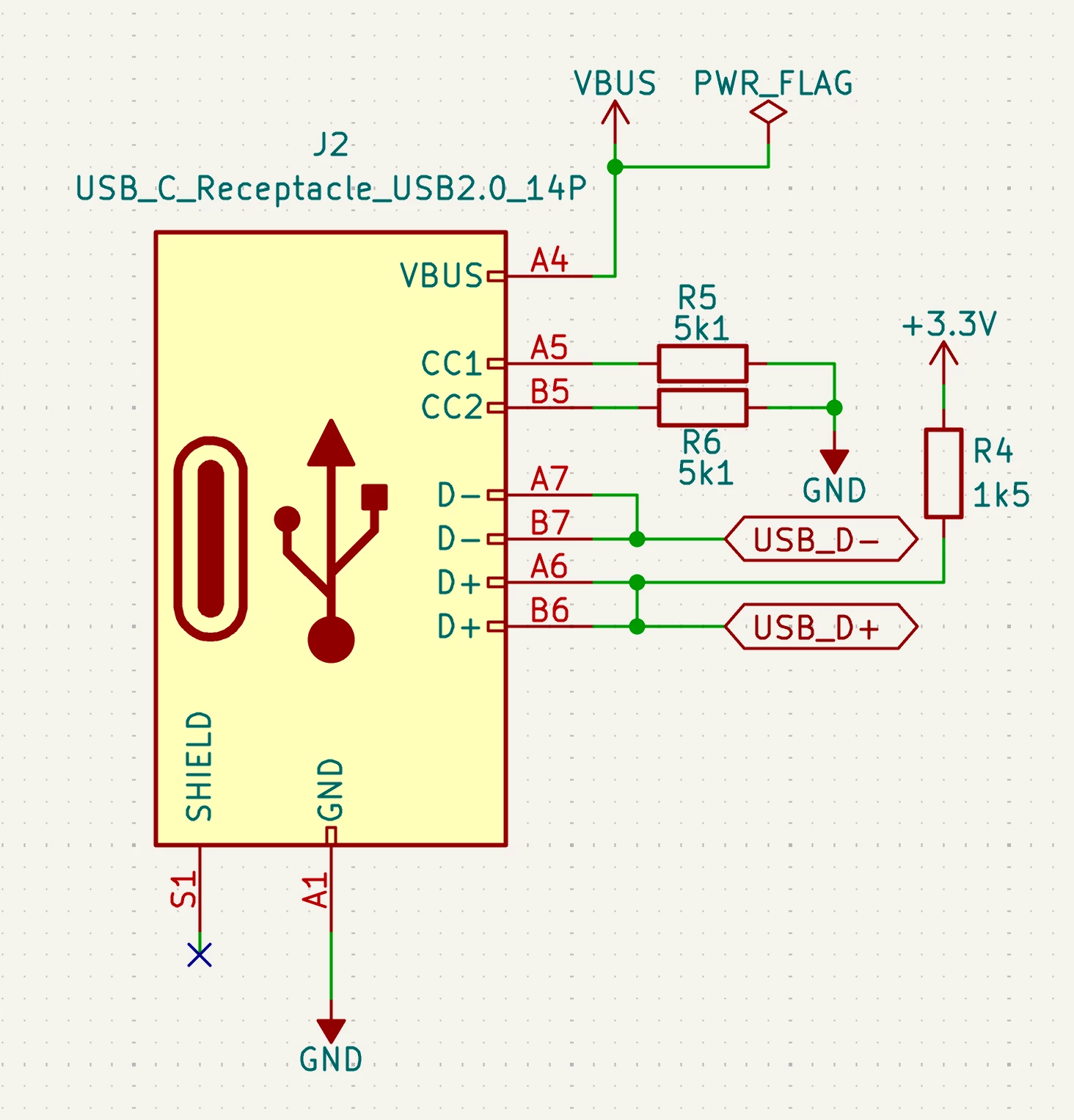
freeflyer_0-1751309545469.png


This topic has been closed for replies.

7 replies

TDK
Jun 30, 2025 10:23 PM UTC

Follow the hardware design guide for this chip family:

https://www.st.com/resource/en/application_note/an4555-getting-started-with-stm32l4-series-and-stm32l4-series-hardware-development-stmicroelectronics.pdf

TDK_0-1751322004770.png

Since VDD = 3.3 V in your design, just use that, as you have.


If your device is bus-powered, no need to check for VBUS voltage. Otherwise, you need to keep USB uninitialized if VBUS is not present.


BOOT0 cannot be connected to the USB-C connector in any functionally useful manner.

The pullup on D+ is not necessary and could cause problems.


If USB is only used for firmware updates, jump to the system bootloader if VBUS is detected.

https://community.st.com/t5/stm32-mcus/how-to-jump-to-system-bootloader-from-application-code-on-stm32/ta-p/49424


"If you feel a post has answered your question, please click ""Accept as Solution""."
freeflyerAuthor
Senior II
Jul 1, 2025 8:02 AM UTC

Thanks TDK

My device is not USB powered, it's battery powered.

USB will only be used for two things:

1. Charging the battery

2. Flashing new firmware

Does this mean I have to take 5V from the USB-C and use a linear regulator to drop it to 3.3V for the VDDUSB pin ?

TDK
Jul 1, 2025 1:55 PM UTC

I would use the 3.3 V rail you already have on the board, as you have done.

You will, however, need to monitor VBUS.

"If you feel a post has answered your question, please click ""Accept as Solution""."
Tesla DeLorean
Guru
Jul 2, 2025 6:24 PM UTC

>>Presumably the VDDUSB is used to indicate to the MCU that the USB cable is connected ? Is VDDUSB used as a signal or for power ?


It's to power the D+/D- pin driver and keep USB Compliance. It allows the rest of the chip to use a 1.8V supply, and have a separate 3.3V for the USB pins. Or the whole thing can run at 3.3V

I think there are separate pull-up/pull-down on the D+/D- pins, check the Data Sheet.

Tips, Buy me a coffee, or three.. PayPal Venmo (See Profile) Up vote any posts that you find helpful, it shows what's working..