Associate
July 14, 2026
Solved

STM32L431 TIM1 PWM output enters Idle State during debugger halt when DBG_TIM1_STOP is enabled?

  • July 14, 2026
  • 10 replies
  • 80 views

Hello,


I am using an STM32L431 and found an interesting behavior with TIM1 PWM output while debugging.


Test conditions:


- MCU: STM32L431

- TIM1 CH2 PWM output

- Debugger: ST-LINK

- Debug halt enabled

- DBGMCU TIM1 freeze enabled (DBG_TIM1_STOP)


Observed behavior:


TIM2:

When the debugger halts the CPU (breakpoint or single-step),

the PWM output keeps its current output state as expected.


TIM1:

When the debugger halts the CPU and TIM1 freeze is enabled,

the PWM output no longer behaves like TIM2.


Additional observations:


1. MOE remains set (MOE = 1).


2. With OSSI = 0:

   the output appears to become high-impedance (or disconnected).


3. With OSSI = 1 and OIS2 = 0:

   the output becomes Low.


4. With OSSI = 1 and OIS2 = 1:

   the output becomes High.


5. If DBG_TIM1_STOP is disabled:

   PWM continues running during debug halt.


These results make it appear that TIM1 enters an Idle/Off-State condition during debugger halt and the output level is determined by OSSI/OIS settings.


Questions:


1. Is this expected behavior of TIM1 advanced timers during debug halt?


2. Is TIM1 output intentionally forced into an Idle State when DBG_TIM1_STOP is active?


3. Is this behavior documented somewhere in the reference manual?


4. Why does TIM2 keep its output state while TIM1 appears to switch to an Idle-State-controlled output?


Any explanation would be appreciated.
 

I checked the STM32L431 errata sheet but could not find any

related limitation regarding TIM1 PWM outputs during debug halt.


Thank you.

Best answer by waclawek.jan

Hi ​@hiroyuki kato ,

I successfully reproduced the described behaviour.

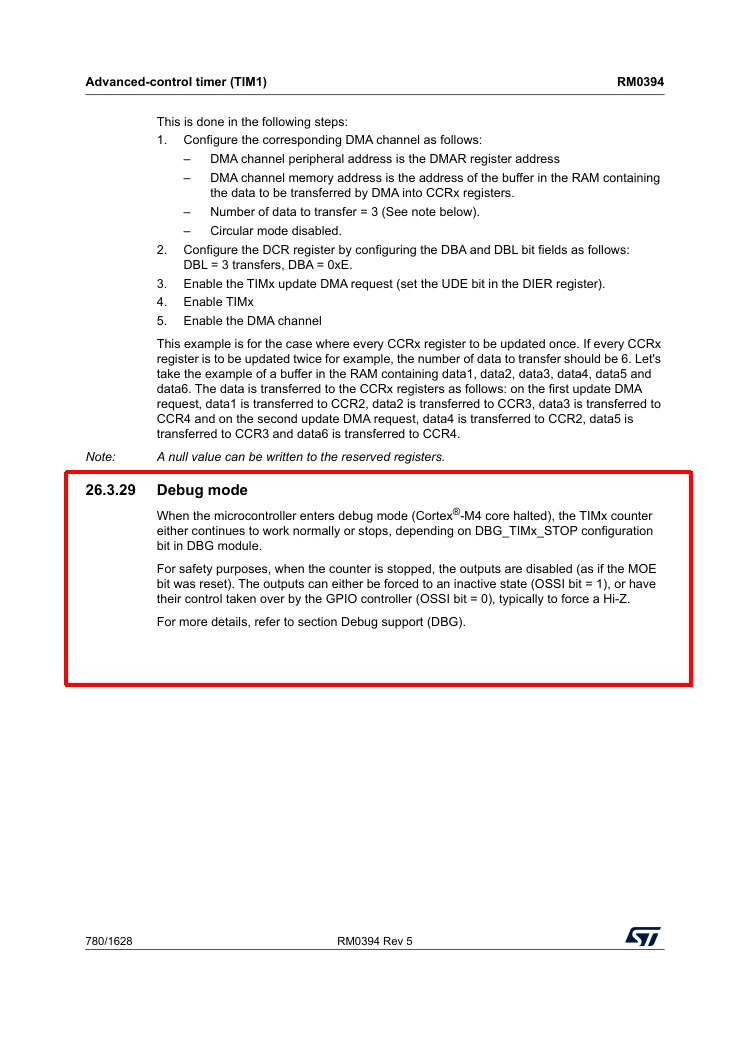
However, turns out, it’s documented:

Yes, it is surprising.

JW

10 replies

MGogr.1
Senior
July 14, 2026

May I know why you want to check PWM Pulses in Debug mode?

Are the pulses not generating as per the requirements?

Associate
July 14, 2026

Thank you for your reply.


The PWM output works correctly during normal operation.

The reason I started investigating this was actually during debugging. I became confused because TIM1 and TIM2 behaved differently when the CPU was halted by the debugger.

With DBG_TIM1_STOP enabled, TIM1 output appears to enter a state controlled by OSSI/OIS settings.


For example:

- OSSI = 1, OIS2 = 0 -> output becomes Low

- OSSI = 1, OIS2 = 1 -> output becomes High


On the other hand, TIM2 keeps its current output state during debug halt and does not show the same behavior.

Initially, I suspected a configuration problem, a Break-related effect, or even an errata issue because the output seemed to become disconnected when OSSI was disabled. This behavior was quite confusing during debugging and made it difficult to understand whether the timer was working correctly.

After further testing, I realized the behavior is related to TIM1-specific features such as OSSI/OIS and possibly the advanced timer output stage.

So my goal is not to solve a PWM generation issue. The PWM itself works correctly.

I would like to understand whether this TIM1 behavior during debug halt is an expected and documented characteristic of the advanced timer architecture, and why it differs from TIM2.

MGogr.1
Senior
July 14, 2026

OK. Understood.

This may be because Both the Timers are on different APB Bus. And Timer1 is 16 bit whereas Timer2 is 32bit.

Associate
July 14, 2026

Thank you.


That makes sense.

What made me suspect an Idle-State-related behavior is that the output level during debug halt changes according to OSSI and OIS settings.


For example:

- OSSI = 1, OIS2 = 0 -> Low

- OSSI = 1, OIS2 = 1 -> High


Also, if DBG_TIM1_STOP is disabled, PWM continues running normally during debug halt.

Because of these observations, it appears that TIM1 output enters some kind of Idle-State-controlled condition when TIM1 is frozen by the debugger.

This behavior initially confused me during debugging because TIM2 does not show the same behavior.

Is that the expected behavior of the advanced timer output stage? Or am I overlooking some configuration that could explain this behavior?


Thank you.

waclawek.jan
Super User
July 14, 2026

> suspected [...] Break-related effect,

And did you rule that out? How do you set up the break-related features? MOE=1 is *after* the pin going to Hi-Z?

Can you please read out and post TIM1 registers content. I’ll try to reproduce.

Which package exactly, and which pin?

Thanks,

JW

Associate
July 15, 2026

Thank you for looking into this.


The current register values are:


TIM1->CR1   = 0x00000081

TIM1->CR2   = 0x00000000

TIM1->CCMR1 = 0x00006000

TIM1->CCER  = 0x00000010

TIM1->SR    = 0x0003001F

TIM1->BDTR  = 0x0200A000


Additional observations:


- Break and Break2 are disabled.

- MOE is set.

- OSSI and OSSR are disabled.


I also performed a pull-up/pull-down test to verify whether the output was truly high-impedance.

With OSSI disabled during debug halt:


- Adding a pull-up resistor forces the pin High.

- Adding a pull-down resistor forces the pin Low.


This was confirmed using an oscilloscope.

Therefore, the TIM1 output appears to become genuinely high-impedance during debug halt rather than simply holding a High or Low level.

Another interesting observation is that enabling OSSI changes the behavior:


- OSSI = 1, OIS2 = 0 -> Low

- OSSI = 1, OIS2 = 1 -> High


This made me suspect that the advanced timer output stage may be entering some kind of Idle-State or Off-State controlled condition during debug halt.

For reference, both timers are configured to freeze during debug halt:

- DBGMCU_APB2FZ_DBG_TIM1_STOP = 1

- DBGMCU_APB1FZR1_DBG_TIM2_STOP = 1


However, TIM2 does not show the same behavior.


Thank you for trying to reproduce this.


Regards,

Hiroyuki Kato

waclawek.jan
waclawek.janBest answer
Super User
July 16, 2026

Hi ​@hiroyuki kato ,

I successfully reproduced the described behaviour.

However, turns out, it’s documented:

Yes, it is surprising.

JW

Associate
July 16, 2026

Thank you very much for taking the time to reproduce the issue and for finding the relevant section in the reference manual.


I had completely overlooked that paragraph.


The behavior now makes perfect sense and matches all of my observations, including the Hi-Z state when OSSI = 0 and the output state controlled by OIS when OSSI = 1.


I really appreciate your help. Thank you for saving me from spending many more hours chasing what I thought might be a configuration issue or an undocumented limitation.


Best regards,

Hiroyuki Kato

waclawek.jan
Super User
July 16, 2026

One more detail: the whole BDTR-related machinery (including MOE) influences only the complementary channels. 

In ‘L4, TIM1_CH4 is *not* complementary, so that will probably remain driven also during the debug freeze.

I did not test this one but I believe I am right with this detail.

JW


ST Technical Moderator
July 16, 2026

 Hello, ​@hiroyuki kato 

The observed behavior appears to be expected.

The key point is that TIM2 and TIM1 are not equivalent timers:

-TIM2 is a general-purpose timer.

-TIM1 is an advanced-control timer.

As a result, they do not necessarily behave in the same way when the CPU is halted in debug mode.

When the CPU is halted, TIM2 typically holds the current output state at the moment of the halt. If the output is high when the debugger pauses execution, it remains high. If the output is low, it remains low.

TIM1 has additional output-control features, such as:

  • MOE: Main Output Enable
  • OSSI: Off-State Selection for Idle mode
  • OSSR: Off-State Selection for Run mode
  • OIS: Output Idle State

Because of these advanced output controls, when TIM1 is frozen during a debug halt, the final pin state can depend on the configured idle or off-state behavior rather than on the instantaneous pulse-width modulation (PWM) level.

For example, in the tested case, TIM1 was configured with OSSI enabled and the idle state set to high. This configuration explains why the output transitions to high when the CPU is halted, even if it is low at that instant.

as ​@waclawek.jan said its documented in 26.3.29 Debug mode section

BR
Gyessine
 

In order to give better visibility on the answered topics, please click on 'Best answer' on the reply which solved your issue or answered your question.
Associate
July 21, 2026

Hello Gyessine and waclawek.jan,


Thank you very much for your replies, and sorry for my late response. I was away on holiday.

I had completely overlooked section 26.3.29 of RM0394.


After reading the documentation and comparing it with my measurements, everything now makes perfect sense, including the Hi-Z behavior when OSSI = 0 and the output state controlled by OSSI/OIS.

I would especially like to thank waclawek.jan for taking the time to reproduce the behavior and point me to the relevant section of the reference manual.


I really appreciate all your help. Without your guidance, I would probably still be searching for a configuration issue or an undocumented limitation.


Thank you again for your time, expertise, and patience.


Best regards,

Hiroyuki Kato