

Pavel Krupets
Associate III
March 13, 2019
Solved

STM32L151VE ADC reads 20% lower value on one of the ADC inputs (channel 18, pin B12)

  • March 13, 2019
  • 17 replies
  • 5671 views

Not sure if I messed something up. Signal is okay (on the pin). No differences with layout compared to other inputs. ADC is at full speed (16 MHz).

On image it is sensor 22 (reads ~2500). Sensor 23, 24, 25 all read normal values (~3000).

Voltages on all those pins is ~2.8V.

VREF, VDDA, VDD = 3.3V.
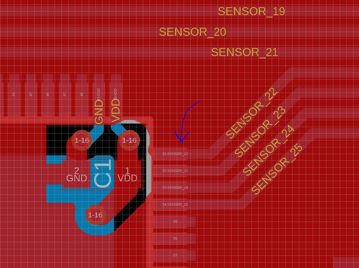
0690X0000087sCRQAY.png

This topic has been closed for replies.
Best answer by MikeDB

Ok what you could do is set up the code to repeatedly measure just one ADC and measure the current through the VDDA pin. Repeat for the good and bad ADCs and see if there is a significant difference. Means lifting the pin but at least it's not a BGA. Can't think of anything else I'm afraid.

17 replies

Uwe Bonnes
Chief
March 13, 2019

Your layout does not help to identify what Port Pins you use. How fast is your sampling? Maybe this is some issue with fast versus slow channels when sampling fast.

AvaTar
Senior III
March 13, 2019

Exactly, there is a charge-up of the S&H capacitor involved.

Too short sample times create a "drag over" or pseudo-crosstalk effect.

Pavel Krupets
Associate III
March 13, 2019

16 MHz (1 mega samples), 4 cycles sampling time.

Only 1 channel out of 24 which are all read in sequence reads lower value (consistently). I moved it around in a sequence but it didn't change anything.

Correction: sampling it multiple times does change the reading.

Pavel Krupets
Associate III
March 13, 2019

Similar problem with 16 cycles sampling time.

MikeDB
Senior II
March 13, 2019

Can we see the top side of the PCB ?

Pavel Krupets
Associate III
March 13, 2019

0690X0000087wCBQAY.png0690X0000087wC6QAI.png

MikeDB
Senior II
March 13, 2019

Actually that's the best connected of the lot. Something the other end of the track maybe ?

MikeDB
Senior II
March 13, 2019

Have you examined the PCB with a magnifying glass and checked you don't have a manufacturing fault on that pin ?

Pavel Krupets
Associate III
March 13, 2019

I checked signal on oscilloscope and it looks just fine. Both ends. Signal is low frequency, analog.

Not a lot of noise in signal lines.

0690X0000087wDJQAY.png

0690X0000087wCzQAI.png

MikeDB
Senior II
March 13, 2019

Yes that looks fine. Faulty IC maybe ? Do you have a second PCB loaded ?

Pavel Krupets
Associate III
March 13, 2019

Checked under stereo microscope (well ones you use for soldering surface mount), didn't see anything suspicious.

Was curious why this stuff can happen, might read it multiple times, it seems 2nd read is better than 1st. Similar to how 1st channel in sequence reads high consistently (10% higher than it should be). This is solved by reading the same channel again immediately after 1st read.
