Question
stm32L051 registers don't change
Hello!
I'm working on a custom board with an stm32L051 and the HSI16 crystal. I'm setting the clock registers, Flash, PWR and then I try to enable the clock for TIM21. as you can see in the code I set the bit but the computer "doesn't listen"(I am looking in the APB2ENR reg in the debugging env). anyone had this issue?
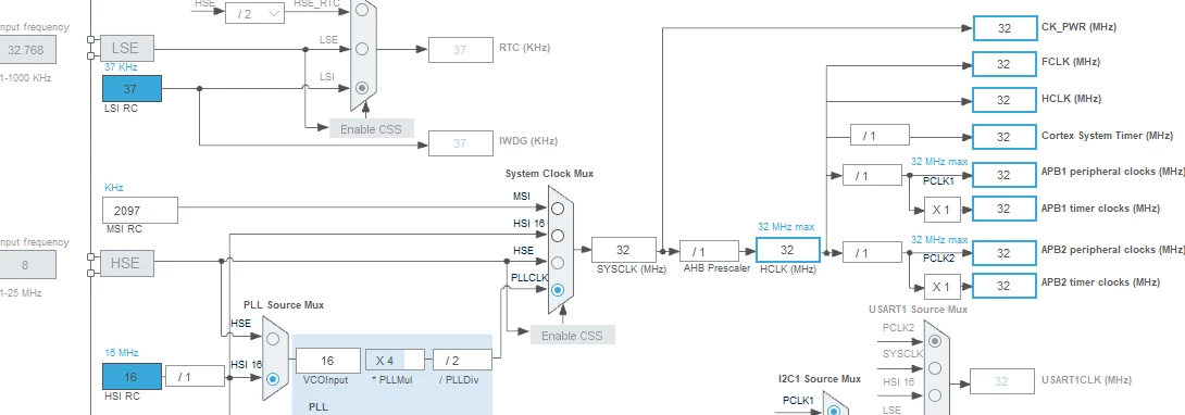
adding the clock diagram and code.
Thanks,
Eyal Porat
The clock setup and FLASH+PWR
void clockSetup(void)
{

	RCC->CR |= (1 << 0); //set the HSI16ON
	while(!(RCC->CR & (1 << 2))); //wait for the HSI16RDYF to set

	RCC->APB1ENR |= (1 << 28); //set the POWERN bit

	PWR->CR |= (1 << 11); //set VOS bits to 0x1

	FLASH->ACR |= (1 << 0); //set the LATENCY bit to 1WS(2cpu cycles)

	FLASH->ACR |= (1 << 1); //set the PERFTEN bit

	FLASH->ACR |= (1 << 6); //set the PRE_READ bit

	uint32_t temp = FLASH ->ACR; //it is recommended to read the register


	RCC->CFGR = 0;

	RCC->CFGR &= ~(15 << 4); //set the AHB prescaler to 1

	RCC->CFGR &= ~(7 << 8); //set the PPRE1/APB1/PCLK1 to div 1

	RCC->CFGR &= ~(7 << 11); //set the PPRE2/APB2/PCLK2 to div 1

	RCC->CFGR |= (1 << 18); //set the PLLMUL scaler to 4

	RCC->CFGR |= (1 << 22); //set the PLLDIV devidor to 2


	RCC->CFGR &= ~(1 << 16); //set the input for the PLL to HSI16

	RCC->CR |= (1 << 24); //set the PLLON bit to enable the PLL

	while(!(RCC->CR & (1 << 25))); //wait for the PLL to get ready


	RCC->CFGR |= (3 << 0); //set the SW bits to 01 (HSI16 input)

	while(!(RCC->CFGR & (3 << 2))); //wait for the clock source to update

	//SystemCoreClockUpdate();

}
The Timer functions
void TIM21conf(void)
{
	//RCC->APB2ENR |= (1 << 2); //enable the TIM21 clock
	RCC->APB2ENR |= RCC_APB2ENR_TIM21EN;
	while(TIM21->ARR == 0);
	//timers clock is 32mhz
	TIM21->PSC = 32000-1; //clock fraquency -1 to get a 1khz pulse
	TIM21->ARR = 0xFFFF; //set the maximum value to be the max possible

	TIM21->CR1 |= (1 << 0); //enable the timer

	while (!(TIM21->SR & (1 << 0))); //wait for the timer ready bit to set
}

void delayMs(uint32_t millis)
{
	TIM21->CNT = 0; //reset the count value

	while (TIM21->CNT <= (millis)); //wait for the timer to reack the pre-set value
}
int main()
{
clockSetup();
SystemCoreClockUpdate();
TIM21conf();
while(1)
{
}
}the main code.