Solved
STM32H750 Quad SPI Flash memory mapped mode. error: data is 0x88.
Hello everyone!
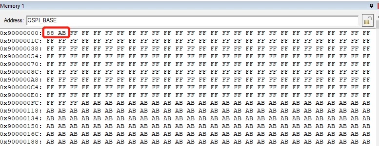
I use the Quad SPI flash of stm32 h750. I write data at a certain address through commands, such as address 0. But after configuring the memory mapping mode, I check that the data at address 0x90000000 is 0x88, while my data is at 0x90000001.
more info:
Use Keil MDK software
My operation:
1.Config Quad SPI
2.Write data (0xAB) to address 0
3.Read data in addre 0 (success)
4.Set memory mapped mode
5.Read data in 0x90000000, data is 0x88(error)
I have two questions:
1.After I write data to address, in the memory mapping mode, the data is at address +1(byte), is this normal?
2.Why can't the operation reach address 0?Seems to be caused by problem 1
Thanks!
My code:
void QUADSPI_Init(void)
{
 /* QUADSPI parameter configuration*/
 stQSpi.Instance = QUADSPI;
 stQSpi.Init.ClockPrescaler = 1;
 stQSpi.Init.FifoThreshold = 4;
 stQSpi.Init.SampleShifting = QSPI_SAMPLE_SHIFTING_HALFCYCLE;
 stQSpi.Init.FlashSize = POSITION_VAL(0X100000)-1;
 stQSpi.Init.ChipSelectHighTime = QSPI_CS_HIGH_TIME_5_CYCLE;
 stQSpi.Init.ClockMode = QSPI_CLOCK_MODE_0;
 stQSpi.Init.FlashID = QSPI_FLASH_ID_1;
 stQSpi.Init.DualFlash = QSPI_DUALFLASH_DISABLE;
 if (HAL_QSPI_Init(&stQSpi) != HAL_OK)
 {
 Error_Handler();
 }
}
void QSPI_Config_Mmap(void)
{
 QSPI_CommandTypeDef Cmdhandler;
 QSPI_MemoryMappedTypeDef stMMPCfg;

 stMMPCfg.TimeOutActivation = QSPI_TIMEOUT_COUNTER_DISABLE;
 stMMPCfg.TimeOutPeriod = 0;

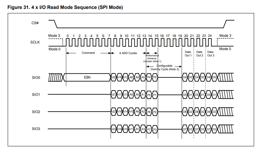
 Cmdhandler.Instruction = 0xEB; //Quad IO Fast Read
 Cmdhandler.Address = 128;
 Cmdhandler.DummyCycles = 4;
 Cmdhandler.InstructionMode = QSPI_INSTRUCTION_1_LINE;
 Cmdhandler.AddressMode = QSPI_ADDRESS_4_LINES;
 Cmdhandler.AddressSize = QSPI_ADDRESS_24_BITS;
 Cmdhandler.DataMode = QSPI_DATA_4_LINES;
 Cmdhandler.SIOOMode=QSPI_SIOO_INST_EVERY_CMD;
 Cmdhandler.AlternateByteMode=QSPI_ALTERNATE_BYTES_NONE;
 Cmdhandler.DdrMode=QSPI_DDR_MODE_DISABLE;
 Cmdhandler.DdrHoldHalfCycle=QSPI_DDR_HHC_ANALOG_DELAY;

 HAL_QSPI_MemoryMapped(&stQSpi,&Cmdhandler,&stMMPCfg);
}


void QspiFlash_Write_Page(uint8_t * pBuffer,uint32_t nWriteAddr, uint16_t nByteNum)
{
 stQSPI_CommandSet stCmdSet;

 QspiFlash_Write_Enable();

 stCmdSet.nCmd=QSPI_FLASH_QuadPageProgram;
 stCmdSet.nInstructionMode = QSPI_INSTRUCTION_1_LINE;
 stCmdSet.nAddrMode = QSPI_ADDRESS_1_LINE;
 stCmdSet.nAddress = nWriteAddr;
 stCmdSet.nAddrSize = QSPI_ADDRESS_24_BITS;
 stCmdSet.nDataMode = QSPI_DATA_4_LINES;
 stCmdSet.nDummyCycles = 0;
 QSPI_Send_CMD(stCmdSet);
 QSPI_Transmit(pBuffer,nByteNum);
 QspiFlash_Wait_Busy();
}