I would like to build a full bridge converter according to attached topology picture. The signals for controlling the switches should be like in the picture pwm_scheme. The frequency should be 500KHz. How to configure TIM1 or TIM8 on STM32H725ZGT6 to achieve this?
To control the current i1 with lowering the duty cycle of the PWM which input is better to use: ETR or BKIN?
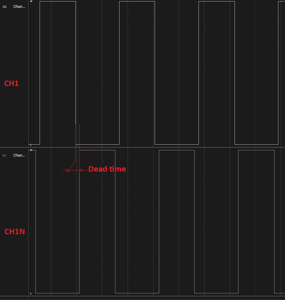
In your case you need to use PWM output with complementary channel for example using CH1 and CH1N outputs by inserting a dead time and duty cycle set at 50%.
ALL OFF→ is the dead time insertion.
This is an example (inspired from NUCLEO-H743ZI\Examples\TIM\TIM_ComplementarySignals) of code to configure TIM1 to generate complementarity PWM signal outputs on CH1 (PE9) and CH1N (PE8):
/* Select the Timer instance */ TimHandle.Instance = TIM1;
TimHandle.Init.Prescaler = <define your prescaler>; TimHandle.Init.Period = <define a period value>; TimHandle.Init.ClockDivision = 0; TimHandle.Init.CounterMode = TIM_COUNTERMODE_UP; TimHandle.Init.RepetitionCounter = 0; if(HAL_TIM_PWM_Init(&TimHandle) != HAL_OK) { /* Initialization Error */ Error_Handler(); }
/*##-2- Configure the PWM channels #########################################*/ /* Common configuration for all channels */ sPWMConfig.OCMode = TIM_OCMODE_PWM1; sPWMConfig.OCPolarity = TIM_OCPOLARITY_HIGH; sPWMConfig.OCNPolarity = TIM_OCNPOLARITY_HIGH; sPWMConfig.OCIdleState = TIM_OCIDLESTATE_SET; sPWMConfig.OCNIdleState = TIM_OCNIDLESTATE_RESET; sPWMConfig.OCFastMode = TIM_OCFAST_DISABLE;
/* Set the pulse value for channel 1 */ sPWMConfig.Pulse = <pulse value = period value / 2 to obtain 50% of duty cycle>; if(HAL_TIM_PWM_ConfigChannel(&TimHandle, &sPWMConfig, TIM_CHANNEL_1) != HAL_OK) { /* Configuration Error */ Error_Handler(); }
/* Set the Break feature & Dead time */ sBreakConfig.BreakState = TIM_BREAK_ENABLE; sBreakConfig.DeadTime = <set your dead time>; sBreakConfig.OffStateRunMode = TIM_OSSR_ENABLE; sBreakConfig.OffStateIDLEMode = TIM_OSSI_ENABLE; sBreakConfig.LockLevel = TIM_LOCKLEVEL_1; sBreakConfig.BreakPolarity = TIM_BREAKPOLARITY_HIGH; sBreakConfig.BreakFilter = 0; sBreakConfig.AutomaticOutput = TIM_AUTOMATICOUTPUT_ENABLE; if(HAL_TIMEx_ConfigBreakDeadTime(&TimHandle, &sBreakConfig) != HAL_OK) { /* Configuration Error */ Error_Handler(); }
In your case you need to use PWM output with complementary channel for example using CH1 and CH1N outputs by inserting a dead time and duty cycle set at 50%.
ALL OFF→ is the dead time insertion.
This is an example (inspired from NUCLEO-H743ZI\Examples\TIM\TIM_ComplementarySignals) of code to configure TIM1 to generate complementarity PWM signal outputs on CH1 (PE9) and CH1N (PE8):
/* Select the Timer instance */ TimHandle.Instance = TIM1;
TimHandle.Init.Prescaler = <define your prescaler>; TimHandle.Init.Period = <define a period value>; TimHandle.Init.ClockDivision = 0; TimHandle.Init.CounterMode = TIM_COUNTERMODE_UP; TimHandle.Init.RepetitionCounter = 0; if(HAL_TIM_PWM_Init(&TimHandle) != HAL_OK) { /* Initialization Error */ Error_Handler(); }
/*##-2- Configure the PWM channels #########################################*/ /* Common configuration for all channels */ sPWMConfig.OCMode = TIM_OCMODE_PWM1; sPWMConfig.OCPolarity = TIM_OCPOLARITY_HIGH; sPWMConfig.OCNPolarity = TIM_OCNPOLARITY_HIGH; sPWMConfig.OCIdleState = TIM_OCIDLESTATE_SET; sPWMConfig.OCNIdleState = TIM_OCNIDLESTATE_RESET; sPWMConfig.OCFastMode = TIM_OCFAST_DISABLE;
/* Set the pulse value for channel 1 */ sPWMConfig.Pulse = <pulse value = period value / 2 to obtain 50% of duty cycle>; if(HAL_TIM_PWM_ConfigChannel(&TimHandle, &sPWMConfig, TIM_CHANNEL_1) != HAL_OK) { /* Configuration Error */ Error_Handler(); }
/* Set the Break feature & Dead time */ sBreakConfig.BreakState = TIM_BREAK_ENABLE; sBreakConfig.DeadTime = <set your dead time>; sBreakConfig.OffStateRunMode = TIM_OSSR_ENABLE; sBreakConfig.OffStateIDLEMode = TIM_OSSI_ENABLE; sBreakConfig.LockLevel = TIM_LOCKLEVEL_1; sBreakConfig.BreakPolarity = TIM_BREAKPOLARITY_HIGH; sBreakConfig.BreakFilter = 0; sBreakConfig.AutomaticOutput = TIM_AUTOMATICOUTPUT_ENABLE; if(HAL_TIMEx_ConfigBreakDeadTime(&TimHandle, &sBreakConfig) != HAL_OK) { /* Configuration Error */ Error_Handler(); }