

jreina
Associate II
May 3, 2024
Solved

STM32H5 RTC count through power cycles

  • May 3, 2024
  • 11 replies
  • 5293 views

What is the expected RTC peripheral behavior through power cycles on VDD? We have a 3.3V system design with the STM32H562VGT6 right now.

Setup:

  • VDD = 3.3V from external supply
  • VBAT = 220mF supercap attached
  • RTC is enabled & counting, system is stable
  • LSE oscillation is active on the PC14/15 lines

Action:

  1. VDD = 0V for 1-2 sec (unplugged PSU)
  2. VDD = 3.3V restored (reconnected PSU)

Expected Behavior Through Power-Cycle:

  • RTC count maintains operation & counting (count increases)
  • LSE signal is oscillating at PC14/15 lines

Observed:

  • RTC count freezes when power is removed & resumes counting when power is restored


Is this expected? Is it possible to keep the RTC counter active & counting through power cycles?
 

This topic has been closed for replies.
Best answer by jreina

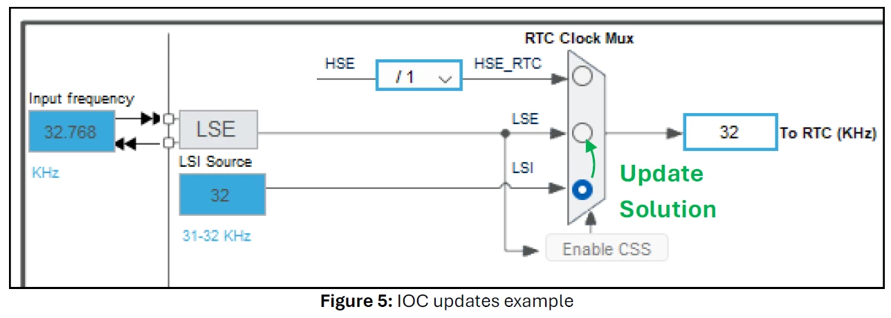
Thank you for the detail and patience @STOne-32@unsigned_char_array, we were able to resolve the situation! Our project was using the LSI within the MSP - 


Solution:


void HAL_RTC_MspInit(RTC_HandleTypeDef* hrtc)
{
 RCC_PeriphCLKInitTypeDef PeriphClkInitStruct = {0};
 if(hrtc->Instance==RTC)
 {
 /** Initializes the peripherals clock
 */
 PeriphClkInitStruct.PeriphClockSelection = RCC_PERIPHCLK_RTC;
 PeriphClkInitStruct.RTCClockSelection = RCC_RTCCLKSOURCE_LSE; // <- Originally 'RCC_RTCCLKSOURCE_LSI'
 if (HAL_RCCEx_PeriphCLKConfig(&PeriphClkInitStruct) != HAL_OK)
 {
 Error_Handler();
 }

 /* Peripheral clock enable */
 __HAL_RCC_RTC_ENABLE();
 __HAL_RCC_RTCAPB_CLK_ENABLE();
 }
}


 Our IOC file wasn't in-sync with our project; is it supposed to be? Here was the update to apply with the IOC - 

Clock Update Example.png


Thank you guys!

11 replies

STOne-32
ST Technical Moderator
May 4, 2024

Dear @jreina ,

This is not expected and is strange behavior , VBAT mode is used exactly for such use cases where we loose main VDD and keep the RTC counting and LSE Oscillation stable . To debug this case, we need to see schematics of power supplies including VBAT , try to monitor the PC13 output of the LSE/Div and see what happens using an oscilloscope probes while probing the VDD supply and PC13 output. As well as the Firmware sequence.

Hope it helps you .

STOne-32

Justin1
Associate III
May 5, 2024

Thank you for the quick response STOne-32!

back shortly

jreina
jreinaAuthor
Associate II
May 7, 2024

Hi STOne-32, here is our problem in further detail. - 


Target:

  • RTC for continuous operation & counts through Vdd power cycles


Circuit:

RTC Debug.png


Source:


/**
 * @brief The application entry point.
 * @retval int
 */
int main(void)
{
	...
	
	HAL_Init();

	...
	
	SystemClock_Config();
	
	...
	
	MX_RTC_Init();

	... 
	
	os/freertos init & start
	
	...
	
	for(;;);
}
	

/**
 * @brief System Clock Configuration
 * @retval None
 */
void SystemClock_Config(void)
{
 RCC_OscInitTypeDef RCC_OscInitStruct = {0};
 RCC_ClkInitTypeDef RCC_ClkInitStruct = {0};

 /** Configure the main internal regulator output voltage
 */
 __HAL_PWR_VOLTAGESCALING_CONFIG(PWR_REGULATOR_VOLTAGE_SCALE3);

 while(!__HAL_PWR_GET_FLAG(PWR_FLAG_VOSRDY)) {}

 /** Configure LSE Drive Capability
 */
 HAL_PWR_EnableBkUpAccess();
 //__HAL_RCC_LSEDRIVE_CONFIG(RCC_LSEDRIVE_LOW);
 __HAL_RCC_LSEDRIVE_CONFIG(RCC_LSEDRIVE_HIGH);

 /** Initializes the RCC Oscillators according to the specified parameters
 * in the RCC_OscInitTypeDef structure.
 */
 RCC_OscInitStruct.OscillatorType = RCC_OSCILLATORTYPE_HSI48|RCC_OSCILLATORTYPE_HSI
									|RCC_OSCILLATORTYPE_LSI|RCC_OSCILLATORTYPE_LSE;
 RCC_OscInitStruct.LSEState = RCC_LSE_ON;
 RCC_OscInitStruct.HSIState = RCC_HSI_ON;
 RCC_OscInitStruct.HSIDiv = RCC_HSI_DIV2;
 RCC_OscInitStruct.HSICalibrationValue = RCC_HSICALIBRATION_DEFAULT;
 RCC_OscInitStruct.LSIState = RCC_LSI_ON;
 RCC_OscInitStruct.HSI48State = RCC_HSI48_ON;
 RCC_OscInitStruct.PLL.PLLState = RCC_PLL_NONE;
 if (HAL_RCC_OscConfig(&RCC_OscInitStruct) != HAL_OK)
 {
	Error_Handler();
 }

 /** Initializes the CPU, AHB and APB buses clocks
 */
 RCC_ClkInitStruct.ClockType = RCC_CLOCKTYPE_HCLK|RCC_CLOCKTYPE_SYSCLK
							 |RCC_CLOCKTYPE_PCLK1|RCC_CLOCKTYPE_PCLK2
							 |RCC_CLOCKTYPE_PCLK3;
 RCC_ClkInitStruct.SYSCLKSource = RCC_SYSCLKSOURCE_HSI;
 RCC_ClkInitStruct.AHBCLKDivider = RCC_SYSCLK_DIV1;
 RCC_ClkInitStruct.APB1CLKDivider = RCC_HCLK_DIV1;
 RCC_ClkInitStruct.APB2CLKDivider = RCC_HCLK_DIV1;
 RCC_ClkInitStruct.APB3CLKDivider = RCC_HCLK_DIV1;

 if (HAL_RCC_ClockConfig(&RCC_ClkInitStruct, FLASH_LATENCY_1) != HAL_OK)
 {
	Error_Handler();
 }
}


/**
 * @brief RTC Initialization Function
 * None
 * @retval None
 */
static void MX_RTC_Init(void)
{
	RTC_PrivilegeStateTypeDef privilegeState = {0};

	/** Initialize RTC Only
	*/
	hrtc.Instance = RTC;
	hrtc.Init.HourFormat = RTC_HOURFORMAT_24;
	hrtc.Init.AsynchPrediv = 127;
	hrtc.Init.SynchPrediv = 255;
	hrtc.Init.OutPut = RTC_OUTPUT_DISABLE;
	hrtc.Init.OutPutRemap = RTC_OUTPUT_REMAP_NONE;
	hrtc.Init.OutPutPolarity = RTC_OUTPUT_POLARITY_HIGH;
	hrtc.Init.OutPutType = RTC_OUTPUT_TYPE_OPENDRAIN;
	hrtc.Init.OutPutPullUp = RTC_OUTPUT_PULLUP_NONE;
	hrtc.Init.BinMode = RTC_BINARY_NONE;

	if (HAL_RTC_Init(&hrtc) != HAL_OK)
	{
		Error_Handler();
	}

	privilegeState.rtcPrivilegeFull = RTC_PRIVILEGE_FULL_NO;
	privilegeState.backupRegisterPrivZone = RTC_PRIVILEGE_BKUP_ZONE_NONE;
	privilegeState.backupRegisterStartZone2 = RTC_BKP_DR0;
	privilegeState.backupRegisterStartZone3 = RTC_BKP_DR0;

	if (HAL_RTCEx_PrivilegeModeSet(&hrtc, &privilegeState) != HAL_OK)
	{
		Error_Handler();
	}

	return;
}


Test:

  1. Power is applied (Vdd=3.3V) and the system stabilizes
  2. Power is removed (Vdd=0V) for 1 second
  3. Power is applied (Vdd=3.3V)

Results:

  1. RTC signal is visible for steps #1-3 above
  2. RTC count starts at #1, halts unexpectedly for #2 and resumes at #3


Why is the RTC time count halting for #2 for us here? This is not expected

STOne-32
ST Technical Moderator
May 7, 2024

Dear @jreina 

thanks for the details . Just wanted to understand what means :

  1. RTC signal is visible for steps #1-3 above ?

is it visible for all steps from 1 to 3 including 2?

if possible to activate the output on PC13 and monitor the LSE clock in continuous way ? As PC13 is powered by backup domain and we should see what happens . Is you can try to change and LSE drive level to low as well to debug further .

ST1

Justin1
Associate III
May 7, 2024

Interesting! Back tomorrow, thank you

STOne-32
ST Technical Moderator
May 29, 2024

Hi @jreina 


Very Glad to see you are able to fix it ! well done.    Continue Releasing your Creativity using STM32 ;)

Ciao

STOne-32.
