


Question
STM32G484 HRTIM: external-event-to-counter-reset latency and conflicting RM0440 timing values
Hello,
I am using an STM32G484RE with HRTIM running at 160 MHz, configured as follows:
- Timer B runs continuously with prescaler
HRTIM_PRESCALERRATIO_MUL32. - External event EEV7 comes from GPIO PB4.
- EEV7 uses rising-edge detection, with digital filtering disabled.
- EEV7 resets Timer B’s counter.
- The same EEV7 event sets Timer C’s output TC1.
- TC1 SET triggers Timer B capture 1.
I need to understand the timing between the external GPIO edge, Timer B counter reset, and TC1 SET/capture.
I found the following differences in RM0440:
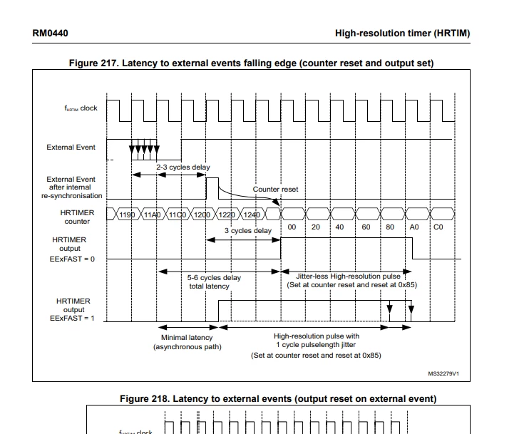
- The older timing diagram, Figure 217 in the edition corresponding to English Rev 7, shows 2–3 HRTIM clock cycles for input resynchronization/counter reset, followed by 3 additional cycles before the output changes.
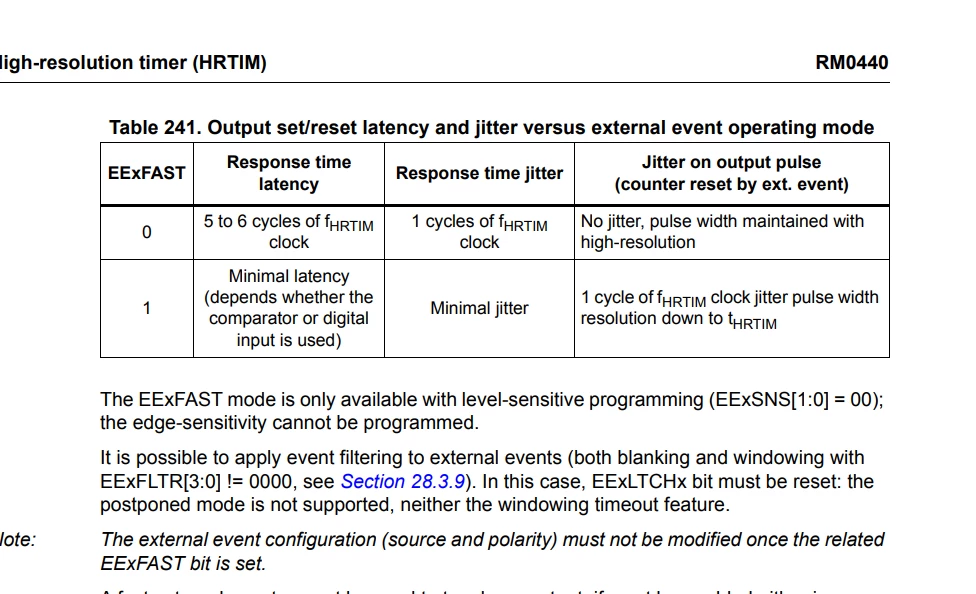
- In RM0440 Rev 9, Table 241 on page 928 lists 5–6 cycles for synchronous output response.
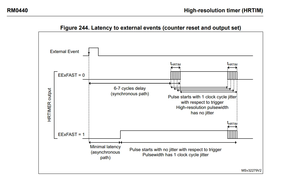
- Figures 244–245 on page 929 instead show 6–7 cycles and no longer show the intermediate counter-reset timing.
Could you clarify
- What is the minimum/maximum latency from the EEV7 GPIO rising edge to Timer B’s counter resetting, for the configuration above? Please specify the timing reference points and whether GPIO/input-path propagation is included.
- Which synchronous output-response value is correct: 5–6 cycles or 6–7 cycles? What accounts for the difference between Table 241 and Figures 244–245?
- Where is the TC1 SET event used by another timer’s capture logic taken from? Is it before or after the output-processing latency shown in Figure 244? Is there additional latency before the receiving timer samples its counter?
- Do these timings depend on the external-event channel, rising versus falling edge, or silicon revision?