

Manu Abraham
Senior
December 28, 2020
Solved

STM32G474RE TIM4 Rotary Encoder

  • December 28, 2020
  • 5 replies
  • 2597 views

Hi,

Greetings!

I have a Bourns Rotary encoder

https://www.bourns.com/docs/product-datasheets/pec11r.pdf

connected to PA11(ENCA)/TIM4_CH1 and PA12(ENCB)/TIM4_CH2.

Trying to use the encoder as a input control for user input.

This is what I am doing:

 
static void encoder_init(void)
{
	LL_GPIO_InitTypeDef		gpio;
 
	LL_APB1_GRP1_EnableClock(LL_APB1_GRP1_PERIPH_TIM4);
 
	gpio.Pin	= LL_GPIO_PIN_11 | LL_GPIO_PIN_12;	/* Enc A, Enc B */
	gpio.Mode	= LL_GPIO_MODE_ALTERNATE;		/* Alternate function */
	gpio.Speed	= LL_GPIO_SPEED_FREQ_LOW;		/* Low Speed */
	gpio.Alternate	= LL_GPIO_AF_10;			/* AF10=TIM4 */
	LL_GPIO_Init(GPIOA, &gpio);
 
	LL_TIM_SetPrescaler(TIM4, 0);
	LL_TIM_SetAutoReload(TIM4, 100);
	LL_TIM_SetCounterMode(TIM4, LL_TIM_COUNTERMODE_UP);
	LL_TIM_SetClockDivision(TIM4, LL_TIM_CLOCKDIVISION_DIV4);
 
	LL_TIM_DisableARRPreload(TIM4);
//	LL_TIM_SetEncoderMode(TIM4, LL_TIM_ENCODERMODE_X4_TI12);
	LL_TIM_SetEncoderMode(TIM4, LL_TIM_ENCODERMODE_DIRECTIONALCLOCK_X1_TI12);
 
	LL_TIM_IC_SetActiveInput(TIM4, LL_TIM_CHANNEL_CH1, LL_TIM_ACTIVEINPUT_DIRECTTI);
	LL_TIM_IC_SetPrescaler(TIM4, LL_TIM_CHANNEL_CH1, LL_TIM_ICPSC_DIV1);
	LL_TIM_IC_SetFilter(TIM4, LL_TIM_CHANNEL_CH1, LL_TIM_IC_FILTER_FDIV2_N8);
	LL_TIM_IC_SetPolarity(TIM4, LL_TIM_CHANNEL_CH1, LL_TIM_IC_POLARITY_RISING);
 
	LL_TIM_IC_SetActiveInput(TIM4, LL_TIM_CHANNEL_CH2, LL_TIM_ACTIVEINPUT_DIRECTTI);
	LL_TIM_IC_SetPrescaler(TIM4, LL_TIM_CHANNEL_CH2, LL_TIM_ICPSC_DIV1);
	LL_TIM_IC_SetFilter(TIM4, LL_TIM_CHANNEL_CH2, LL_TIM_IC_FILTER_FDIV2_N8);
	LL_TIM_IC_SetPolarity(TIM4, LL_TIM_CHANNEL_CH2, LL_TIM_IC_POLARITY_RISING);
 
	LL_TIM_EnableCounter(TIM4);
	LL_TIM_CC_EnableChannel(TIM4, LL_TIM_CHANNEL_CH1);
	LL_TIM_CC_EnableChannel(TIM4, LL_TIM_CHANNEL_CH2);
}
 
int main(void)
{
	uint32_t enc_cur = 0, enc_prev = 0;
 
	LL_APB2_GRP1_EnableClock(LL_APB2_GRP1_PERIPH_SYSCFG);
	LL_APB1_GRP1_EnableClock(LL_APB1_GRP1_PERIPH_PWR);
 
	NVIC_SetPriorityGrouping(NVIC_PRIORITYGROUP_4);
	SystemClock_Config();
	gpio_init();
	uart_init();
 
	encoder_init();
	printf("\tSTM32G474 Encoder Test\n");
 
	while (1) {
		enc_cur = LL_TIM_GetCounter(TIM4);
		if (enc_cur != enc_prev) {
			printf(" ENC: %d DIR: %d\n", enc_cur, LL_TIM_GetDirection(TIM4) >> 4);
			enc_prev = enc_cur;
		}
	}
}

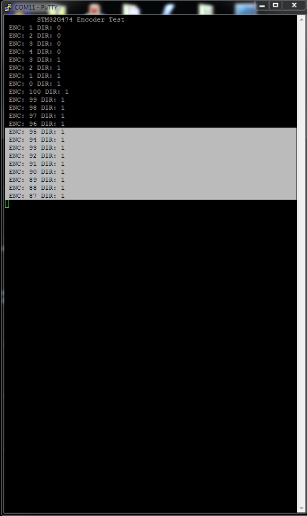
On RST, I get the following results:

       STM32G474 Encoder Test

 ENC: 1 DIR: 0

 ENC: 2 DIR: 0

 ENC: 3 DIR: 0

 ENC: 4 DIR: 0

When I turn the encoder CW, I get:

 ENC: 3 DIR: 1

 ENC: 2 DIR: 1

 ENC: 1 DIR: 1

 ENC: 0 DIR: 1

 ENC: 100 DIR: 1

 ENC: 99 DIR: 1

 ENC: 98 DIR: 1

 ENC: 97 DIR: 1

 ENC: 96 DIR: 1

When I turn the encoder CCW, I get:

 ENC: 95 DIR: 1

 ENC: 94 DIR: 1

 ENC: 93 DIR: 1

 ENC: 92 DIR: 1

 ENC: 91 DIR: 1

 ENC: 90 DIR: 1

 ENC: 89 DIR: 1

 ENC: 88 DIR: 1

 ENC: 87 DIR: 1

Attached screenshot:
0693W000006Gx0VQAS.png 

Despite what I do, the direction, does not seem to change.

Any thoughts, suggestions what I am doing wrong in here ?

Thanks,

Manu

This topic has been closed for replies.
Best answer by waclawek.jan

This looks much like there's no input on CH2.

JW

5 replies

waclawek.jan
Super User
December 28, 2020

I don't understand the Cube/LL gibberish, but

> LL_TIM_ENCODERMODE_DIRECTIONALCLOCK_X1_TI12

is probably Directional Clock encoder mode, which, as the manual says:

In the “directional clock�? mode on Figure 409, the clocks are provided on two lines, with a

single one at once, depending on the direction, so as to have one up-counting clock line and

one down-counting clock line.

which is not case with the usual manually turned encoder.

JW

Manu Abraham
Senior
December 28, 2020

Hi JW,

Thanks for the input. Which mode do you suggest ?

I tried both SMS=b'0011' and b'1110' both appeared to have weird results:

ie,

static void encoder_init_r2(void)
{
	LL_GPIO_InitTypeDef		gpio;
 
	LL_APB1_GRP1_EnableClock(LL_APB1_GRP1_PERIPH_TIM4);
 
	gpio.Pin	= LL_GPIO_PIN_11 | LL_GPIO_PIN_12;	/* Enc A, Enc B */
	gpio.Mode	= LL_GPIO_MODE_ALTERNATE;		/* Alternate function */
	gpio.Speed	= LL_GPIO_SPEED_FREQ_LOW;		/* Low Speed */
	gpio.Alternate	= LL_GPIO_AF_10;			/* AF10=TIM4 */
	LL_GPIO_Init(GPIOA, &gpio);
 
	LL_TIM_SetPrescaler(TIM4, 0);
	LL_TIM_SetAutoReload(TIM4, 100);
	LL_TIM_SetCounterMode(TIM4, LL_TIM_COUNTERMODE_UP);
	LL_TIM_SetClockDivision(TIM4, LL_TIM_CLOCKDIVISION_DIV4);
 
	LL_TIM_DisableARRPreload(TIM4);
 
	/**
	 * Slave Mode Selection (SMS)
	 * 0000: Slave mode disabled ifCEN = ‘1 prescaler fed from internal clock.
	 * 0001: Encoder mode 1 - tim_ti1fp1 edge up/down counter depending on tim_ti2fp2 level.
	 * 0010: Encoder mode 2 - tim_ti2fp2 edge up/down counter depending on tim_ti1fp1 level.
	 * 0011: Encoder mode 3 - tim_ti1fp1, tim_ti2fp2 edge up/down counter depending on the level of the other input.
	 * 0100: Reset Mode - selected trigger input rising edge (tim_trgi) reinitializes counter and updates registers.
	 * 0101: Gated Mode - The counter clock is enabled when the trigger input (tim_trgi) is high.
	 * 0110: Trigger Mode - The counter starts at a rising edge of the trigger tim_trgi (but it is not reset). Only the start of the counter is controlled.
	 * 0111: External Clock Mode 1 - Rising edges of the selected trigger (tim_trgi) clock the counter.
	 * 1000: Combined reset + trigger mode - Rising edge of the selected trigger input (tim_trgi) reinitializes the counter, generates an update of the registers and starts the counter.
	 * 1001: Combined gated + reset mode - The counter clock is enabled when the trigger input (tim_trgi) is high. The counter stops and is reset) as soon as the trigger becomes low.
	 * 1010: Encoder mode: Clock plus direction, x2 mode.
	 * 1011: Encoder mode: Clock plus direction, x1 mode, tim_ti2fp2 edge sensitivity is set by CC2P.
	 * 1100: Encoder mode: Directional Clock, x2 mode.
	 * 1101: Encoder mode: Directional Clock, x1 mode, tim_ti1fp1 and tim_ti2fp2 edge sensitivity is set by CC1P and CC2P.
	 * 1110: Quadrature encoder mode: x1 mode, counting on tim_ti1fp1 edges only, edge sensitivity is set by CC1P.
	 * 1111: Quadrature encoder mode: x1
	 *
	 * #define TIM_SMCR_SMS_0 (0x00001UL << TIM_SMCR_SMS_Pos) // 0x00000001
	 * #define TIM_SMCR_SMS_1 (0x00002UL << TIM_SMCR_SMS_Pos) // 0x00000002
	 * #define TIM_SMCR_SMS_2 (0x00004UL << TIM_SMCR_SMS_Pos) // 0x00000004
	 * #define TIM_SMCR_SMS_3 (0x10000UL << TIM_SMCR_SMS_Pos) // 0x00010000
	 *
	 * #define LL_TIM_ENCODERMODE_X2_TI1 TIM_SMCR_SMS_0 // Quadrature encoder mode 1, x2 mode - Counter counts up/down on TI1FP1 edge depending on TI2FP2 level
	 * #define LL_TIM_ENCODERMODE_X2_TI2 TIM_SMCR_SMS_1 // Quadrature encoder mode 2, x2 mode - Counter counts up/down on TI2FP2 edge depending on TI1FP1 level
	 * #define LL_TIM_ENCODERMODE_X4_TI12 (TIM_SMCR_SMS_1 | TIM_SMCR_SMS_0) // Quadrature encoder mode 3, x4 mode - Counter counts up/down on both TI1FP1 and TI2FP2 edges depending on the level of the other input
	 * #define LL_TIM_ENCODERMODE_CLOCKPLUSDIRECTION_X2 (TIM_SMCR_SMS_3 | TIM_SMCR_SMS_1) // Encoder mode: Clock plus direction - x2 mode
	 * #define LL_TIM_ENCODERMODE_CLOCKPLUSDIRECTION_X1 (TIM_SMCR_SMS_3 | TIM_SMCR_SMS_1 | TIM_SMCR_SMS_0) // Encoder mode: Clock plus direction, x1 mode, TI2FP2 edge sensitivity is set by CC2P
	 * #define LL_TIM_ENCODERMODE_DIRECTIONALCLOCK_X2 (TIM_SMCR_SMS_3 | TIM_SMCR_SMS_2) // Encoder mode: Directional Clock, x2 mode
	 * #define LL_TIM_ENCODERMODE_DIRECTIONALCLOCK_X1_TI12 (TIM_SMCR_SMS_3 | TIM_SMCR_SMS_2 | TIM_SMCR_SMS_0) // Encoder mode: Directional Clock, x1 mode, TI1FP1 and TI2FP2 edge sensitivity is set by CC1P and CC2P
	 * #define LL_TIM_ENCODERMODE_X1_TI1 (TIM_SMCR_SMS_3 | TIM_SMCR_SMS_2 | TIM_SMCR_SMS_1) // Quadrature encoder mode: x1 mode, counting on TI1FP1 edges only, edge sensitivity is set by CC1P
	 * #define LL_TIM_ENCODERMODE_X1_TI2 (TIM_SMCR_SMS_3 | TIM_SMCR_SMS_2 | TIM_SMCR_SMS_1 | TIM_SMCR_SMS_0) // Quadrature encoder mode: x1 mode, counting on TI2FP2 edges only, edge sensitivity is set by CC1P
	 */
 
//	LL_TIM_SetEncoderMode(TIM4, LL_TIM_ENCODERMODE_X4_TI12);	/* Enc MODE3: Up/Down on TI1FP1, TI2FP2 edges */
	LL_TIM_SetEncoderMode(TIM4, LL_TIM_ENCODERMODE_X1_TI1);		/* Enc x1 MODE: Up/Down on TI1FP1 edge */
 
	LL_TIM_IC_SetActiveInput(TIM4, LL_TIM_CHANNEL_CH1, LL_TIM_ACTIVEINPUT_DIRECTTI);
	LL_TIM_IC_SetPrescaler(TIM4, LL_TIM_CHANNEL_CH1, LL_TIM_ICPSC_DIV1);
	LL_TIM_IC_SetFilter(TIM4, LL_TIM_CHANNEL_CH1, LL_TIM_IC_FILTER_FDIV2_N8);
	LL_TIM_IC_SetPolarity(TIM4, LL_TIM_CHANNEL_CH1, LL_TIM_IC_POLARITY_RISING);
 
	LL_TIM_IC_SetActiveInput(TIM4, LL_TIM_CHANNEL_CH2, LL_TIM_ACTIVEINPUT_DIRECTTI);
	LL_TIM_IC_SetPrescaler(TIM4, LL_TIM_CHANNEL_CH2, LL_TIM_ICPSC_DIV1);
	LL_TIM_IC_SetFilter(TIM4, LL_TIM_CHANNEL_CH2, LL_TIM_IC_FILTER_FDIV2_N8);
	LL_TIM_IC_SetPolarity(TIM4, LL_TIM_CHANNEL_CH2, LL_TIM_IC_POLARITY_RISING);
 
	LL_TIM_EnableCounter(TIM4);
	LL_TIM_CC_EnableChannel(TIM4, LL_TIM_CHANNEL_CH1);
	LL_TIM_CC_EnableChannel(TIM4, LL_TIM_CHANNEL_CH2);
}

which results in

#1. With

   LL_TIM_SetEncoderMode(TIM4, LL_TIM_ENCODERMODE_X4_TI12);   /* Enc MODE3: Up/Down on TI1FP1, TI2FP2 edges */

On RST

      STM32G474 Encoder Test

ENC: 1 DIR: 0

ENC: 2 DIR: 0

ENC: 1 DIR: 1

ENC: 2 DIR: 0

ENC: 1 DIR: 1

ENC: 2 DIR: 0

ENC: 1 DIR: 1

ENC: 2 DIR: 0

ENC: 1 DIR: 1

ENC: 2 DIR: 0

On Single CW rotation:

ENC: 3 DIR: 0

ENC: 2 DIR: 1

On Single CCW rotation

ENC: 3 DIR: 0

ENC: 2 DIR: 1

4x CW rotations

ENC: 3 DIR: 0

ENC: 2 DIR: 1

ENC: 3 DIR: 0

ENC: 2 DIR: 1

ENC: 3 DIR: 0

ENC: 2 DIR: 1

ENC: 3 DIR: 0

ENC: 2 DIR: 1

4x CCW rotations

ENC: 3 DIR: 0

ENC: 2 DIR: 1

ENC: 3 DIR: 0

ENC: 2 DIR: 1

ENC: 3 DIR: 0

ENC: 2 DIR: 1

ENC: 3 DIR: 0

ENC: 2 DIR: 1

#2. With

   LL_TIM_SetEncoderMode(TIM4, LL_TIM_ENCODERMODE_X1_TI1);      /* Enc x1 MODE: Up/Down on TI1FP1 edge */

On RST

       STM32G474 Encoder Test

On Single CW rotation:

 ENC: 1 DIR: 0

 ENC: 0 DIR: 1

On Single CCW rotation:

 ENC: 1 DIR: 0

 ENC: 0 DIR: 1

Both dont look quite sane. Or am I still doing something wrong ?

Thanks,

Manu

waclawek.jan
waclawek.janBest answer
Super User
December 28, 2020

This looks much like there's no input on CH2.

JW

Manu Abraham
Senior
December 28, 2020

Hi JW,

I was getting pretty frustrated -- Connected a scope to ENC_A and _B, things looked very well indeed.

Pulled a few hairs not knowing what to do.

Checked CH1 , CH2 waveforms on PA11, 12.

Well, as you said: one channel was dead .. The connector on CH2 was not making contact.

Changed the connector, things look quite good indeed.

Thanks a bunch! I would have lost quite a lot of hair, if not for your observation. ;)

Something really bad happened over here. After I did my last post; We had an electrical issue here, complete blackout, UPS tripped. :\

Resuming after fixing the problem, the filesystem has a previous version of main.c, ie, it was missing the newer

encoder_init_r2() function.

Had to copy back the function from the forum. :)

It looks quite well.

One issue though, it starts with the set auto reload value (ie at max, in this case 100)

Any thoughts to get it start with, say 0 ?

       STM32G474 Encoder Test

 ENC: 100 DIR: 1

 ENC: 0 DIR: 0

 ENC: 1 DIR: 0

 ENC: 2 DIR: 0

 ENC: 3 DIR: 0

 ENC: 4 DIR: 0

 ENC: 5 DIR: 0

 ENC: 6 DIR: 0

 ENC: 7 DIR: 0

 ENC: 6 DIR: 1

 ENC: 5 DIR: 1

 ENC: 4 DIR: 1

 ENC: 3 DIR: 1

 ENC: 2 DIR: 1

 ENC: 1 DIR: 1

 ENC: 0 DIR: 1

 ENC: 100 DIR: 1

 ENC: 99 DIR: 1

 ENC: 98 DIR: 1

 ENC: 97 DIR: 1

Thanks again,

Manu

Manu Abraham
Senior
December 28, 2020

The quick hack, that I did was to set the counter to 1.

Wonder, whether that's a good thing to do ..

Thanks,

Manu