


Solved
STM32G431: SAI as master receiver + DMA, channel swap after restart
Heyho,
next G4 problem…
G431 with an audio ADC (TI’s PCM1822) connected to SAI1_Block_A, SAI is in master receiver mode, meaning it provides the I2S clocks for the external ADC.
DMA is used, circular, 32-bit.
Signals looking good at all audio sampling frequencies, up to 192 kHz.
Problem:
always at 1st start, and every now and then after a SAI + DMA stop and restart, somehow the 2 ADC channels are swapped.
I checked all I2S signals with a scope, and data is always where it’s supposed to be.
I can check the DMA buffer, it’s definitely the SAI.
BAD buffer / channels swapped,
signal connected to RIGHT ( = R ) channel only,
so LEFT should be 0

      L     R     L     R     L     R     L     R
000: +0.31 -0.00 +0.37 +0.00 +0.38 -0.00 +0.36 -0.00
008: +0.30 -0.00 +0.20 -0.00 +0.09 -0.00 -0.04 -0.00


GOOD buffer: L = 0, R = signal
      L     R     L     R     L     R     L     R
000: +0.00 +0.26 +0.00 +0.16 +0.00 +0.04 -0.00 -0.09
008: +0.00 -0.20 -0.00 -0.30 -0.00 -0.36 +0.00 -0.38
our analyzer:
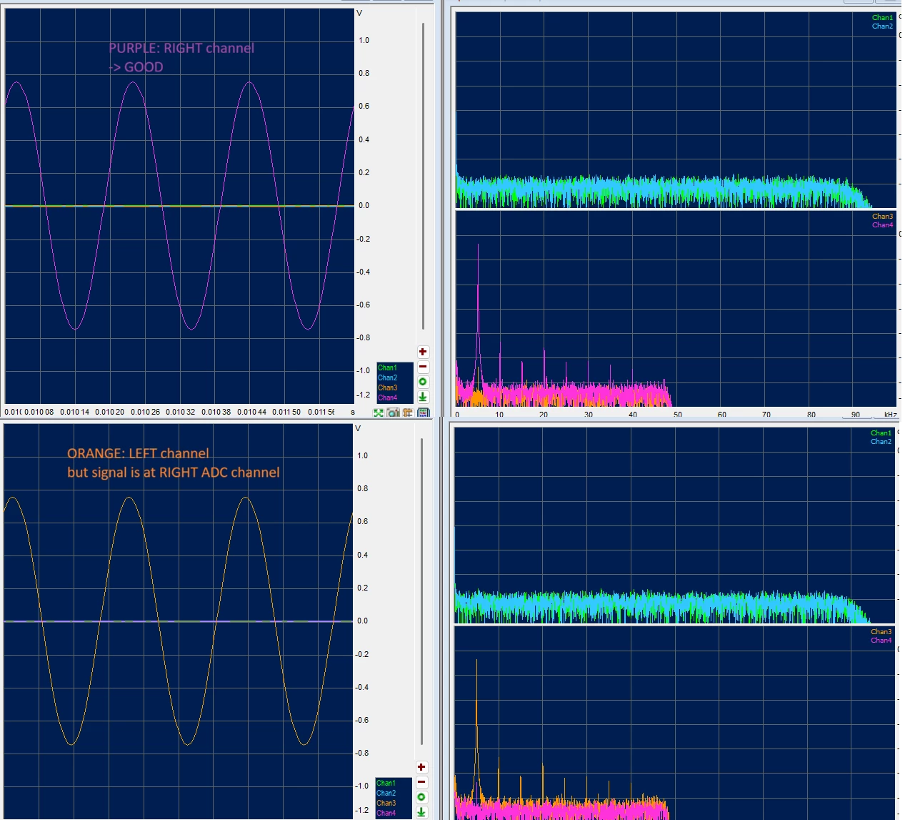
Here are the DMA + SAI start and stop functions:
/* +++++++++++++++++++++++++++++++++++++++++++++++++++++++++++++++++++++++ */
/* SAI_1_A: I2S -> RX = ADC <-> DMA start */
uint8_t SaiAdcDmaStart(void)
{
	if( (1 == u8AdcDmaActive) ||
		((SAI_ADC_12->CR1 & SAI_xCR1_SAIEN) != 0) )
	{
		#if DEBUG_SAI_ERR
			uart_printf(SZC_TEXT_ERR "SaiAdcDmaStart() active\n\r");
		#endif 	/* DEBUG_SAI_ERR */

		return HAL_ERROR;
	}

	/* reset DMA RX complete flags */
	u8AdcDmaRxHalfCplt 	= 0;
	u8AdcDmaRxCplt 		= 0;

	/* DMA buffer pointer reset */
	u16AdcDmaBufPtr = 0;

	/* DMA error counter reset */
	u32SaiIrqErrCnt = 0;

	/* clear DMA flags */
	DMA1->IFCR = DMA_IFCR_CGIF1;

	DMA1_Channel1->CPAR 	= (uint32_t)&(SAI_ADC_12->DR);
	DMA1_Channel1->CMAR 	= (uint32_t)&i32AdcInBuf[0];
	DMA1_Channel1->CNDTR 	= (uint32_t)AUDIO_DMA_BUF_SIZE;

	/* DMA enable */
	DMA1_Channel1->CCR |= DMA_CCR_EN;

	/* peripheral DMA enable */
	SAI_ADC_12->CR1 |= SAI_xCR1_DMAEN;

	/* SAI 1 A enable */
	SAI_ADC_12->CR1 |= SAI_xCR1_SAIEN;

	u8AdcDmaActive = 1;

	return HAL_OK;
}


/* +++++++++++++++++++++++++++++++++++++++++++++++++++++++++++++++++++++++ */
/* SAI_1_A: I2S -> RX = ADC <-> DMA stop */
uint8_t SaiAdcDmaStop(void)
{
	uint8_t u8RetVal = 0;
	uint32_t u32TickStart = HAL_GetTick();

	/* disable */
	SAI_ADC_12->CR1 &= ~SAI_xCR1_DMAEN;
	SAI_ADC_12->CR1 &= ~SAI_xCR1_SAIEN;

	/* wait */
	while( (SAI_ADC_12->CR1 & SAI_xCR1_SAIEN) != 0 )
	{
		if( (HAL_GetTick() - u32TickStart) > (uint32_t)SAI_TO_DISABLE_MS ) break;
	}
	/* check */
	if( (SAI_ADC_12->CR1 & SAI_xCR1_SAIEN) != 0 )
	{
		#if DEBUG_SAI_ERR
			uart_printf(SZC_TEXT_ERR "SaiAdcDmaStop() SAIEN != 0\n\r");
		#endif 	/* DEBUG_SAI_ERR */

		u8RetVal = HAL_ERROR;
	}

	DMA1_Channel1->CCR &= ~DMA_CCR_EN;

	u8AdcDmaActive = 0;

	/* clear DMA flags */
	DMA1->IFCR = DMA_IFCR_CGIF1;

	return u8RetVal;
}
And here’s the SAI and DMA init:
/* ++++++++++++++++++++++++++++++++++++++++++++++++++++++++++++++++++++++++++++++ */
/* SAI 1 A
 *	ADC IN
 *	init
 */
void Sai1AdcInit(void)
{
	Sai1AdcIoDmaInit();

	/* reset registers */
	SAI_ADC_12->CR1 	= 0;
	SAI_ADC_12->CR2 	= 0;
	SAI_ADC_12->FRCR 	= 0;
	SAI_ADC_12->SLOTR 	= 0;

	/* CR1: most important settings here
	 *	HAL init: 088B02E1 with DMA & SAI enables
	 *	DMA and SAI enable are set when started
	 *	MCKEN 	= 0  	-> no MCLK used
	 *	OSR 	= 0  	-> x256
	 *	MCKDIV 	= 8	 	-> depends on clock
	 *	NODIV 	= 1
	 *	SYNCEN 	= 00 	-> async mode
	 *	CKSTR	= 1	 	-> I2S: sample on SCK rising
	 *	DS		= 111	-> data size 32 bit
	 *	PRTCFG 	= 00 	-> "free" protocol -> I2S
	 *	MODE 	= 01 	-> master receiver
	 */
	SAI_ADC_12->CR1 = ( 	SAI_xCR1_MCKDIV_3 |
							SAI_xCR1_NODIV |
							SAI_xCR1_CKSTR |
							SAI_xCR1_DS |
							SAI_xCR1_MODE_0 );

	/* FRCR: frame configuration -> FS = LRCK
	 *	HAL init: 00031F3F
	 *	FSOFF 	= 1  	-> 1 bit offset for I2S		#### MUST for PCM1822 ####
	 *	FSPOL 	= 1	 	-> FS is active high (rising edge)
	 *	FSDEF 	= 1		-> FS signal is a start of frame signal + channel side identification
	 *	FSALL[6:0] 	= 32 -1 -> Frame synchronization active level length
	 *	FRL[7:0]	= 64 -1 -> Frame length
	 */
	SAI_ADC_12->FRCR 	= ( SAI_xFRCR_FSPOL | SAI_xFRCR_FSDEF |
							SAI_xFRCR_FSOFF |
							((32 - 1) << SAI_xFRCR_FSALL_Pos) |
							((64 - 1) << SAI_xFRCR_FRL_Pos) );

	/* SLOTR: slot configuration
	 *	HAL init: FFFF0180
	 *	SLOTEN[15:0] 	= 3 	-> slot enable 1 & 2
	 *	NBSLOT[3:0] 	= 1 +1 	-> number of slots in an audio frame
	 *	SLOTSZ[1:0]		= 10 	-> 32b slot size
	 *	FBOFF[4:0]		= 0 	-> first bit offset
	 */
	SAI_ADC_12->SLOTR 	= ( ((3) << SAI_xSLOTR_SLOTEN_Pos) |
								((1) << SAI_xSLOTR_NBSLOT_Pos) |
								SAI_xSLOTR_SLOTSZ_1 );
}


/* ++++++++++++++++++++++++++++++++++++++++++++++++++++++++++++++++++++++++++++++ */
/* SAI
 *	GPIO & DMA init
 */
void Sai1AdcIoDmaInit(void)
{
	/* ++++++++++++++++++++++++++++++++++++++++++++++++++++ */
	if( (RCC->APB2ENR & RCC_APB2ENR_SAI1EN) != RCC_APB2ENR_SAI1EN )
	{
		__IO uint32_t u32TmpReg;

		RCC->APB2ENR |= RCC_APB2ENR_SAI1EN;
		u32TmpReg = ( RCC->APB2ENR & RCC_APB2ENR_SAI1EN );
		(void)u32TmpReg;
	}

	GPIO_InitTypeDef GPIO_InitStruct = { 0 };

	/* ++++++++++++++++++++++++++++++++++++++++++++++++++++ */
	/** SAI1_A_Block_A GPIO Configuration
		PA8		------> SAI1_SCK_A
		PA9 	------> SAI1_FS_A
		PA10	------> SAI1_SD_A
		MCLK not used
	*/
	GPIO_InitStruct.Pin 		= SAI_1_SCLK_Pin | SAI_1_LRCK_Pin | SAI_1_A_DATA_Pin;
	GPIO_InitStruct.Mode 		= GPIO_MODE_AF_PP;
	GPIO_InitStruct.Pull 		= GPIO_NOPULL;
	GPIO_InitStruct.Speed 		= GPIO_SPEED_FREQ_HIGH;
	GPIO_InitStruct.Alternate 	= GPIO_AF14_SAI1;
	HAL_GPIO_Init(GPIOA, &GPIO_InitStruct);


	/* ++++++++++++++++++++++++++++++++++++++++++++++++++++ */
	/* DMA init */

	DMA1_Channel1->CCR 		= 0;
	DMA1_Channel1->CPAR 	= (uint32_t)&(SAI_ADC_12->DR);
	DMA1_Channel1->CMAR 	= (uint32_t)i32AdcInBuf;
	DMA1_Channel1->CNDTR 	= 0;	/* later = (uint32_t)AUDIO_DMA_BUF_SIZE; */

	/* CCR
	 *	PL priority level:		= 11 = very high
	 *	MSIZE memory size:		= 10 = 32b
	 *	PSIZE periph size:		= 10 = 32b
	 *	MINC memory increment 	= 1
	 *	CIRC circular mode 		= 1
	 *	DIR read from periph 	= 0
	 *	interrupt enables:
	 *		TEIE transfer error 	= 1
	 *		HTIE half transfer 		= 1
	 *		TCIE transfer complete 	= 1
	 */
	DMA1_Channel1->CCR 	= ( DMA_CCR_PL_1 | DMA_CCR_PL_0 |
							DMA_CCR_MSIZE_1 | DMA_CCR_PSIZE_1 |
							DMA_CCR_MINC |
							DMA_CCR_CIRC |
							DMA_CCR_TEIE | DMA_CCR_HTIE | DMA_CCR_TCIE );

	/* DMA MUX
	 *	ATTENTION: MUX channel = DMA channel - 1
	 */
	DMAMUX1_Channel0->CCR = DMA_REQUEST_SAI1_A;

	/* clear DMA flags */
	DMA1->IFCR = DMA_IFCR_CGIF1;
}
Anybody any ideas?
Thanks in advance!