Tommino
Associate III
March 28, 2022
Solved

STM32G4 DMAMUX

Hello,

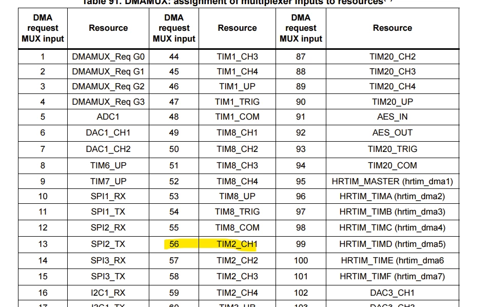
Can you help me to use the DMAMUX in the STM32G474 microcontroller?

How can I program the uC to make TIM2_CH1 sends a DMA request when CC. I have found this in the reference manual but I can't undesrtand which channel of the DMA is involved. Thanks for the clarification 0693W00000LvzUZQAZ.png

This topic has been closed for replies.
waclawek.jan
waclawek.janBest answer
Super User
May 6, 2022

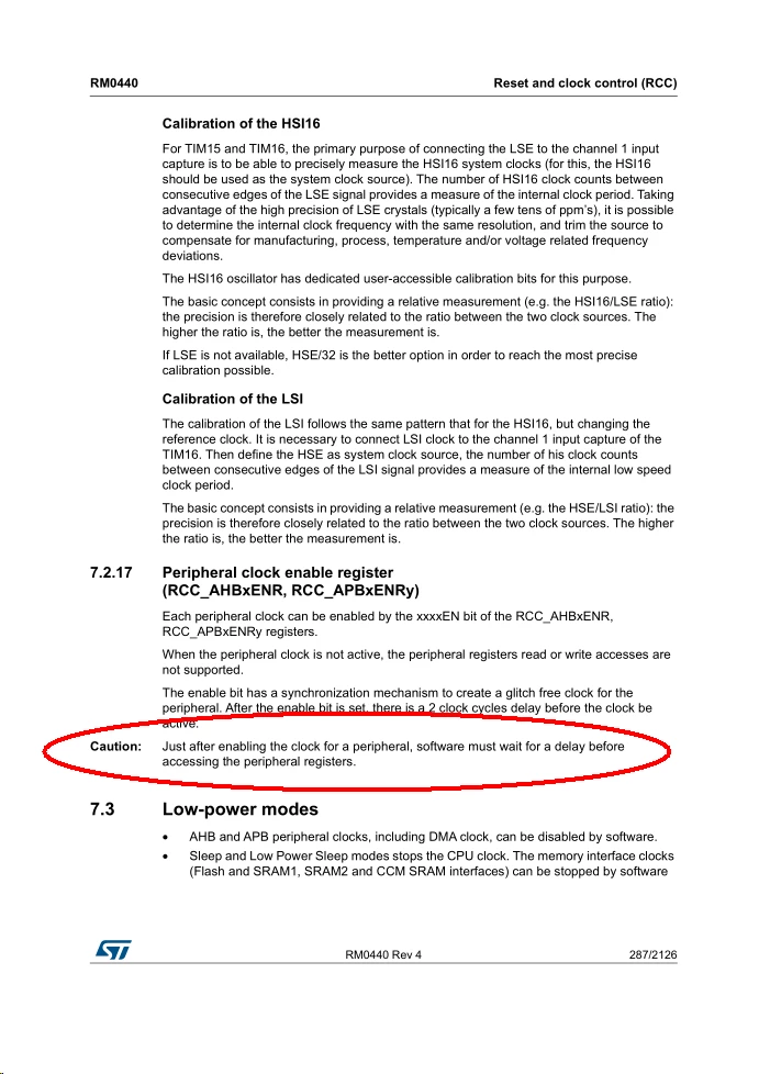
0693W00000NpSASQA3.pngProblem is, that there's no good documented way for this wait. ST published this as errata for older STM32 families, and some of the proposed workarounds are known to not work (and ST does not care, as usually). ST's "libraries" are usually inefficient enough so that timing issues such as these simply never come up.

You can try to insert a couple of NOPs, or dummy reads. A bulletproof solution would be to loop writing and reading back one DMAMUX register utnil it reads back the value written.

What I do is, that I enable all peripheral clocks for peripherals used in the given application early in the program, starting with GPIOs' clocks; then I initialize all GPIOs, then I do any other peripheral initialization. I don't subscribe to the "everything related to given peripheral should be changed at one place" notion (related to my reluctance to use any "abstraction" in microcontrollers).

JW

21 replies

Tommino
TomminoAuthor
Associate III
May 6, 2022

Hi @Community member​ and @TDK​,

In order to use the DMAMUX properly, did I forget anything?

For what concerns the DMAMUX I just enabled its clock and set the REQ_ID but the DMA transfer does not work in my code. Do I forget anything in the settings of the DMAMUX?

waclawek.jan
Super User
May 7, 2022

Read out and check/post TIM2, DMAMUX and DMA registers content.

JW

Tommino
TomminoAuthor
Associate III
May 10, 2022

Hi @Community member​ 

I would like to have TIM2_CH1 and TIM2_CH2 to trigger a DMA transfer, from memory to SPI1 and SPI2 respectively, when the timer has output compare events.

Basically when looking at the SPI1 and SPI2 pins I can see the SPI clock but I do not see the MOSI output. Moreover if I change the CCR1 and CCR2 values of TIM2 I can't see the SPI clock busrts rate changing.

So, I guess there are two problems: one regarding the DMA trasnfer (maybe something wrong in the DMAMUX?) and another one in the registers output compare channels.

Here the registers (I am using Nucleo G474RE)

0693W00000Npg4YQAR.png0693W00000Npg4iQAB.png0693W00000Npg2EQAR.png0693W00000Npg5CQAR.png

waclawek.jan
Super User
May 10, 2022

Binary view of values is not very useful, especially if it cuts the end of the numbers. Switch to hexadecimal.

When I write "check/post registers", I mostly mean "check, and if you don't see anything wrong, post".

What is the timer period and the SPI clock rate?

If you don't see output on MOSI, check/post also the GPIO setting of MOSI pin.

JW

Tommino
TomminoAuthor
Associate III
May 10, 2022

Sorry @Community member​ 

here the values shown correctly

0693W00000NpgOeQAJ.png0693W00000NpgQZQAZ.png0693W00000NpgR3QAJ.png0693W00000NpgQtQAJ.png0693W00000NpgQjQAJ.png

waclawek.jan
Super User
May 10, 2022

What is the timer period and the SPI clock rate?

0693W00000Nph1aQAB.png 

These are quite high addresses (in 'G474, if I am correct, RAM ends in the CCMRAM alias, at 0x2001FFFF). How exactly do you set them? Aren't those arrays local variables, i.e. located at stack? What is their content?

JW

Tommino
TomminoAuthor
Associate III
May 10, 2022

@Community member​

Honestly this is out from my little understanding of microcontroller but I am more than happy to try to understand.

What I did in my code is creating a buffer (to be transferred with SPI) of uint16t with the math.h header and the sin function. Maybe this is not suitable for a microcontroller...

I do not receive any error after building, but I see this message in the window in the right side after clicking debug

0693W00000NphtrQAB.png

#include "math.h"
int main(void)
{
 /* USER CODE BEGIN 1 */
	
		double seno[n];
		double coseno[n];
		uint16_t DACin_Sin[n];
		uint16_t DACin_Cos[n];
		uint16_t i=0;
		 while (i<n)
		 {
 
			seno[i]= sin(i*2*3.1416/n+theta*3.14/180)+1; 
		 	coseno[i]= cos(i*2*3.1416/n)+1; 
			DACin_Sin[i]= seno[i]*(pow (2,N))/(2*k);
			DACin_Cos[i]=coseno[i]*(pow (2,N))/(2*k);
		 	i++;
		 }

waclawek.jan
Super User
May 10, 2022

0693W00000Nph3lQAB.png 

OK so you have SPIx_CR1.BIDIMODE set, and BIDIOE clear, which means you are in halfduplex, Rx mode, that's why clocks are output continuously, regardless of DMA.

Are you sure you want to use halfduplex SPI? It's rather tricky.

Get SPI working first, without DMA, with software polling.

JW

Tommino
TomminoAuthor
Associate III
May 10, 2022

Hi @Community member​ 

As you pointed out, there was the error about the SPI MODE half duplex. It was a typo that I did when I was trying the cube MX enviroment and I erronously set that SPI mode.

Eventually the FW regarding the TIM2, the DMA and the SPI now works correctly.

Thanks a lot for your help

waclawek.jan
Super User
May 10, 2022

> Honestly this is out from my little understanding of microcontroller

This is more a general C/programming issue than specifically microcontroller-related.

For DMA buffers, use arrays defined as global variables, i.e. outside any function (usually at the beginning of given source .c file).

As it is defined now it will work, as main() is the higher-most function and will never exited, but it's a not good practice for various reasons I am not going to detail at the moment.

JW