Associate
March 10, 2025
Solved

STM32G0B1CET can't connect under SWD

  • March 10, 2025
  • 3 replies
  • 1687 views

Hi,

I have built a handful  of STM32 designs before and never had a chip fail to connect. I can't seem to get any connection in Cube Programmer at all:

jakobnator_0-1741569762772.png

  • VDD,VREF+,VBAT is at 3.3V, VSS is connected to ground.
  • NRST is high at boot
  • I can see current drop from 17mA to 7mA (at 12V) when pulling NRST low , so it seems like MCU is doing something.
  • I originally connected with a JLINK but just bought a STLINKV3 SET with the same result.
  • Using SWD over a tag connect
  • tried every connect option in cube programmer (mode/reset mode)
  • I see SWCLK,SWDIO, and NRST working on an oscilloscope, although I haven't bothered decoding the signals.
  • I confirmed chip orientation
  • I confirmed SWCLK,SWDIO, and NRST pins
  • I confirmed my STLINK was updated
  • Checked for shorts under microscope

Schematic:
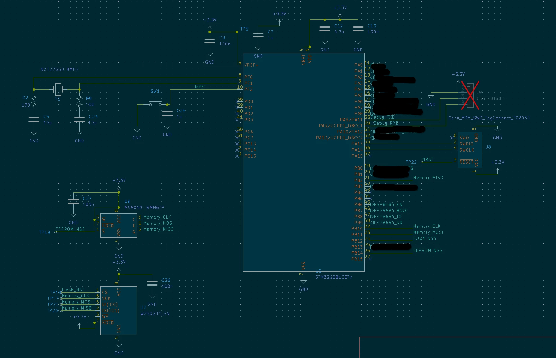
jakobnator_1-1741571188367.png

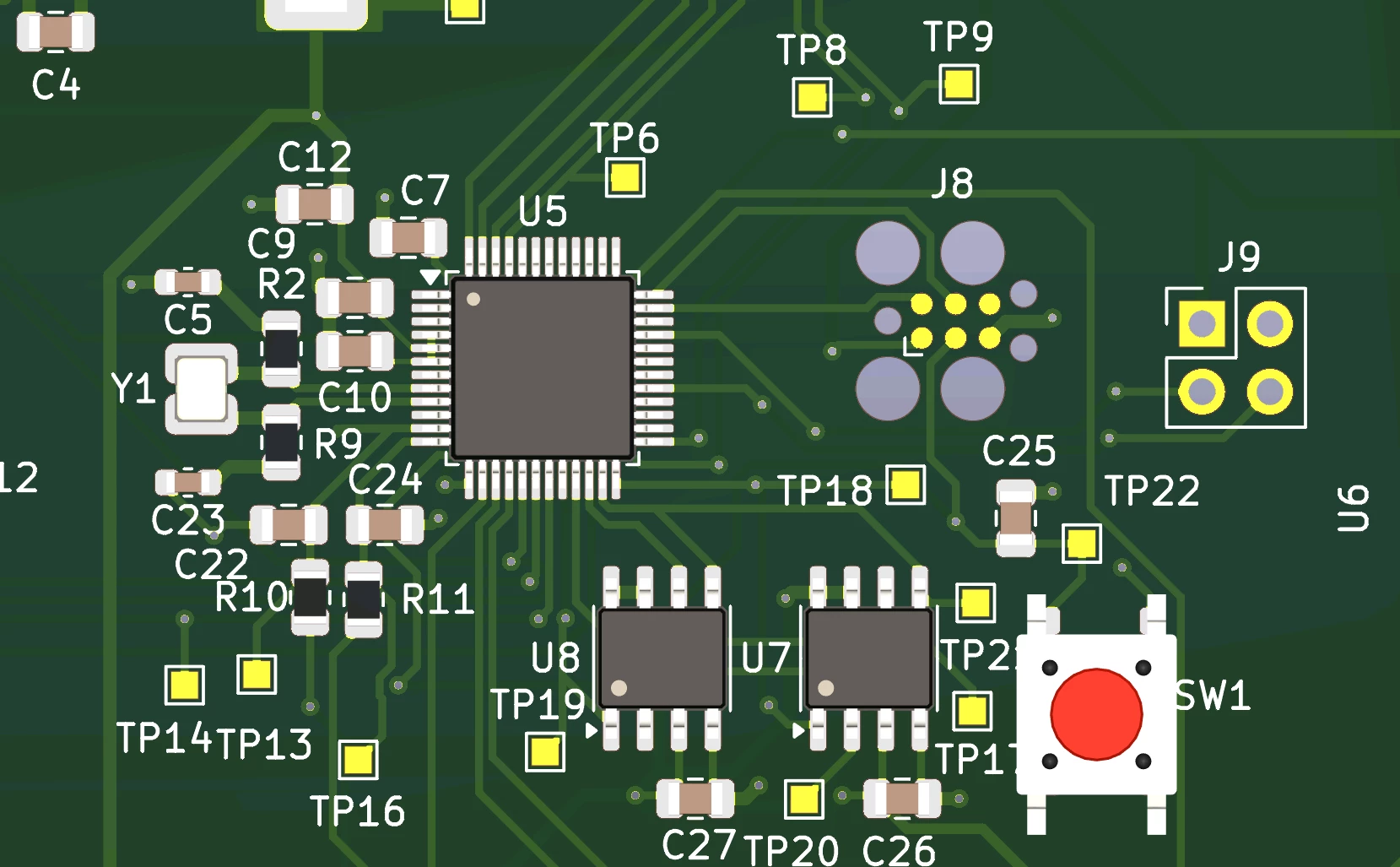
Layout:

jakobnator_2-1741571236810.png


I am pretty much out of ideas at this point, hoping its something *** I missed and need a second set of eyes :)


Any new ideas would be appreciated!
This topic has been closed for replies.
Best answer by jakobnator

Figured it out:


I accidentally used the "STM32G0B1CET6N" instead of "STM32G0B1CET6" variant when selecting parts for the BOM. Which does not have VDDIO connected internally and instead goes to pin 20.


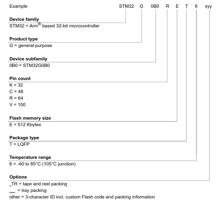
I (poorly) assumed anything in the option field of the part number was related to packaging info. Kind of a footgun IMO there are pin to pin compatibility differences in the last letter of a part number. My datasheet doesn't even mention it in the ordering info:


jakobnator_0-1742096496261.png

My fault regardless!


-Jakob

3 replies

TDK
March 10, 2025

I looked through everything but can't see anything wrong.

Since you probed power, and verified SWD activity, that narrows things down quite a bit. Sure there are no shorts or cold solder joints? A large in focus picture of the board may help.

"If you feel a post has answered your question, please click ""Accept as Solution""."
Associate
March 11, 2025

Hi TDK,

here is a picture of the board. Also I forgot to mention I had two boards assembled and they both have the same issue so I am hesitant it is a solder joint issue. I also inspected it under a microscope and it looked good, I don't have a way to capture through the microscope lens though.

jakobnator_0-1741662893672.png


Another theory I have is somehow the STM32s I received had RDP enabled?

jakobnatorAuthorBest answer
Associate
March 16, 2025

Figured it out:


I accidentally used the "STM32G0B1CET6N" instead of "STM32G0B1CET6" variant when selecting parts for the BOM. Which does not have VDDIO connected internally and instead goes to pin 20.


I (poorly) assumed anything in the option field of the part number was related to packaging info. Kind of a footgun IMO there are pin to pin compatibility differences in the last letter of a part number. My datasheet doesn't even mention it in the ordering info:


jakobnator_0-1742096496261.png

My fault regardless!


-Jakob