STM32F746-Disco I2C Touch Panel ID replying with 0x00 CMSIS-only
STM32F746-Disco
Capacitive Touch Panel FT5336
STM32CubeIDE, Windows 10
CMSIS-only
I'm developing my first I2C driver for STM32F746 using CMSIS-only, and I've decided it would be great to test my I2C skills on built-in capacitive touch panel FT5336. I used ST-provided ft5336.c/.h to get register addresses (since FT5336 datasheet actually doesn't have them). So obviously my first thing to try is to read Chip ID register.
Initially, I've developed DMA driver for it (yeah I can do DMA but still haven't tried I2C), but as I was running into an issue, I made a step back and went full blocking way. Interestingly enough, the results were identical.
What I do:
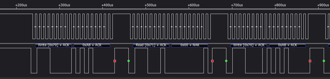
I write slave address in write mode (ACK), followed by ID register (NACK).
Then I give it a little pause (~30us, well above datasheet ~10us for start setup; tried different).
Then I write slave address in read mode (ACK), and receive 0x00 (NACK).
I've carefully examined my signal with oscilloscope and logic analyzer, made sure timings are correct and all. I can write (master send) as much as I want (including with DMA), but I'm failing at reading, it seems. I'm not sure on what side the error is. Obviously, the panel works if I run TouchGFX project on it. I looked at TouchGFX-generated code in case I see something there, but I didn't find anything that would stand out to me. I don't have any other I2C-device at hand to test it with.
I2C3 setup:
void i2c_setup(I2C_TypeDef *I2C) {

	I2C->CR1 &= ~I2C_CR1_PE; //make sure the peripheral is off

	/*
	 * Analog filter enables, digital noise filter disabled
	 * Interrupts disabled
	 * */
	I2C->CR1 = 0x00; //reset
	I2C->CR1 |= (0x00 << I2C_CR1_ANFOFF_Pos) | (0x00 << I2C_CR1_DNF_Pos);

	/*
	 * Set WRITE mode
	 * 7-bit mode (ADD10=0)
	 * Load 7-bit Slave Address
	 */
	I2C->CR2 = 0x00; //reset
	I2C->CR2 |= (0x00 << I2C_CR2_RD_WRN_Pos) | (FT5336_I2C_SLAVE_ADDRESS << I2C_CR2_SADD_Pos);

	/*
	 * TIMING
	 * 100kHz I2C
	 * */
	I2C->TIMINGR = 0x00; //reset
	I2C->TIMINGR |= (0x06 << I2C_TIMINGR_PRESC_Pos) | (0x02 << I2C_TIMINGR_SCLDEL_Pos) | (0x00 << I2C_TIMINGR_SDADEL_Pos) | (0x1E << I2C_TIMINGR_SCLH_Pos)
			| (0x2A << I2C_TIMINGR_SCLL_Pos);

	I2C->CR1 |= I2C_CR1_PE; //activate peripheral

}
void i2c_sendByte(uint8_t data, I2C_TypeDef *I2C) {
I2C->CR2 &= ~I2C_CR2_NBYTES; //make sure number of bytes to transmit is cleared
I2C->CR2 |= (0x01 << I2C_CR2_NBYTES_Pos); //set number of bytes to send to 1
I2C->CR2 |= I2C_CR2_AUTOEND; //stop bit after sent byte
I2C->CR2 &= ~I2C_CR2_RD_WRN; //master requests write transfer
while (!(I2C->ISR & I2C_ISR_TXE)); //wait while transmit data register is empty (just in case, whatever)
//Slave address set in setup
I2C->TXDR = data;
I2C->CR2 |= I2C_CR2_START; //set start bit
}
void i2c_receiveByte(uint8_t *data, I2C_TypeDef *I2C) {
I2C->CR2 &= ~I2C_CR2_NBYTES; //make sure number of bytes to transmit is cleared
I2C->CR2 |= (0x01 << I2C_CR2_NBYTES_Pos); //set number of bytes to 1
I2C->CR2 |= I2C_CR2_AUTOEND; //stop bit after sent byte
I2C->CR2 |= I2C_CR2_RD_WRN; //master requests write transfer
I2C->CR2 |= I2C_CR2_START; //set start bit
while (!(I2C->ISR & I2C_ISR_RXNE)); //wait while receive data register is not empty
*data = I2C->RXDR;
}How I actually run it all in main.c (removed irrelevant UART pieces that work):
i2c_setup(I2C3);
uint8_t i2c3_id_register;
while (1) {
		while (I2C3->ISR & I2C_ISR_BUSY);
		for (uint32_t i = 0; i < 1000; i++); //lame pause
		i2c_sendByte(0xA8, I2C3);
		while (I2C3->ISR & I2C_ISR_BUSY);
		for (uint32_t i = 0; i < 1000; i++); //lame pause
		i2c_receiveByte(&i2c3_id_register, I2C3);

	}
The screenshot if from the logic analyzer, so I actually see what's physically happening on the line, processing the data is not an issue here. Scope gave the same picture. I'm not sure about what I'm doing wrong.