

Eetu Piukkula
Associate III
June 28, 2018
Question

STM32F7 and CAN bus implementation

  • June 28, 2018
  • 7 replies
  • 4809 views
Posted on June 28, 2018 at 20:48

Hi,

so I am using STM32F769xxx MCU with TI's CAN transreceiver (

http://www.ti.com/lit/ds/symlink/sn65hvd232.pdf

, see 232 version, the one without low power modes). I have 2 problems that may have something to do with each other.

1) I have simple program just to spam something to Tx pin of the MCU (what it says is not important here). When I probe that pin with oscilloscope I can see the message. When I probe Rx pin I can see the same exact message. Since this is not connected to any device on the bus there should not be returning traffic. Why I can see same message on both Rx and Tx pins?

2) Heres schematic of CAN implementation:
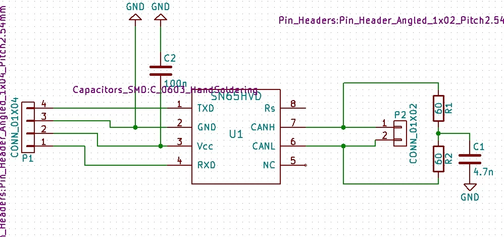
0690X00000604a3QAA.jpg

On the right hand side there are Tx, Rx, GND and Vcc. Vcc is solid 3.29V. On the left there are CAN H and L. When I probe either CAN H/L I see contineus 2.3V voltage. No differential signal, nor any signal at all. At first I had problem with Vcc, that was 2.96V, under the abs.min. 3.0V. Then the voltage on these lanes was bit lower 2.1V. Why does this transreceiver transmit data to the bus side?

I am quite lost with this one. I cannot see anything wrong with my eyes.

Edit: No loopback mode is activated, CAN's operating mode is normal.

Thanks beforehand

--eetu

    This topic has been closed for replies.

    7 replies

    Tesla DeLorean
    Guru
    June 28, 2018
    Posted on June 28, 2018 at 20:54

    >>Why I can see same message on both Rx and Tx pins?

    So you can see the traffic on the bus, and make a determination if another node has precedence over you, or that your signal is going out cleanly. It is a half-duplex channel, only one device should be actively transmitting.

    Tips, Buy me a coffee, or three.. PayPal Venmo (See Profile) Up vote any posts that you find helpful, it shows what's working..
    Eetu Piukkula
    Associate III
    June 28, 2018
    Posted on June 28, 2018 at 21:04

    There is nothing connected to the bus. Nothing should be replaying it back. The point where this is measured is between MCU and TI. After TI only thing that I can see is steady 2.3V.

    Mark Peter Vargha
    Associate III
    June 29, 2018
    Posted on June 29, 2018 at 06:27

    There is nothing connected to the bus.

    There is your device on the bus. ;) But you could test nothning with one node. Use two nodes minimum.

    Read more here:

    https://en.wikipedia.org/wiki/CAN_bus

     
    Eetu Piukkula
    Associate III
    June 28, 2018
    Posted on June 28, 2018 at 21:17

    Here is a picture of this marvelous piece of HW. I haveruled every HW bug out except that TI chip itself is broken, but it was hand soldered straight from the reel so this should not be the case.

    0690X0000060PHoQAM.jpg

    T J
    Senior III
    June 28, 2018
    Posted on June 29, 2018 at 01:53

    SN65HVD230 and SN65HVD231:

    RS :            Mode select pin: strong pull down to GND = high speed mode, strong

    pull up to VCC = low power mode, 10kΩ to 100kΩ pull down to GND = slope control mode

    is your RS pin floating ?

    Eetu Piukkula
    Associate III
    June 29, 2018
    Posted on June 29, 2018 at 08:46

    Yes, that pin is not connected. But that does not matter since I am using SN65HVD232. That version does not support slew rate control.