

STM32F4xx InputCapture and DMA
MCU: STM32F446RE
BOARD: NUCLEO-64 STM32F446
STM32 CUBEMX Version:4.20.0
Library: STM43F4 1.15.0
------------------------------------------------------------------------------------------------------------------------------------------------------------
The problem here is probably hal driver.
I am currently setting TIM1 as PWM Input mode following the examples in STM32Cube_FW_F4_V1.15.0
In the beginning, I am using IT like in the example, it works fine.
However, the pwm signal I want to measure runs at 800KHz.
This forces me to use DMA method to capture the values of TIM_CC1 and TIM_CC2.
the settings of TIM1 DMA is as followed:
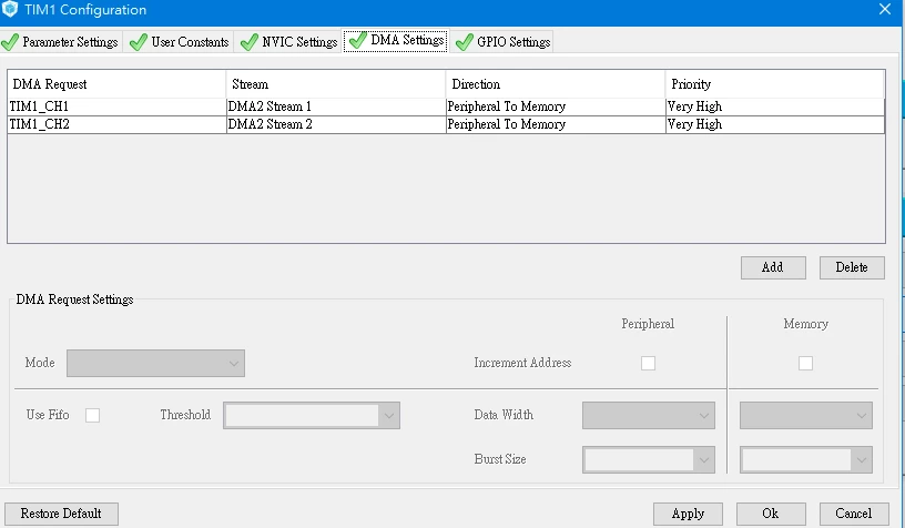
After generation of the project,
I thought that the following code would start the dma data moving:
HAL_TIM_IC_Start_DMA(&htim1, TIM_CHANNEL_2, (uint32_t *)IC2_Buf, IC_PREXFER_COUNT);
HAL_TIM_IC_Start_DMA(&htim1, TIM_CHANNEL_1, (uint32_t *)IC1_Buf, IC_PREXFER_COUNT);But it does not work as:
HAL_TIM_IC_Start_IT(&htim1, TIM_CHANNEL_1);
HAL_TIM_IC_Start_IT(&htim1, TIM_CHANNEL_2);Because inside the HAL_TIM_IC_START_DMA(), there is some code controlling timerHandle state:
HAL_StatusTypeDef HAL_TIM_IC_Start_DMA(TIM_HandleTypeDef *htim, uint32_t Channel, uint32_t *pData, uint16_t Length)
{ /* Check the parameters */ assert_param(IS_TIM_CCX_INSTANCE(htim->Instance, Channel)); assert_param(IS_TIM_DMA_CC_INSTANCE(htim->Instance));if((htim->State == HAL_TIM_STATE_BUSY))
{
return HAL_BUSY;
}
else if((htim->State == HAL_TIM_STATE_READY)) { if((pData == 0U) && (Length > 0)) { return HAL_ERROR; } else { htim->State = HAL_TIM_STATE_BUSY; } }...
}
This meas that if I call HAL_TIM_IC_Start_DMA(&htim1, TIM_CHANNEL_1,...) first, the htim1 would be in HAL_BUSY state, therefore I cannot successfully call HAL_TIM_IC_Start_DMA(&htim1, TIM_CHANNEL_2,...) accordingly.
I tried to comment out those hal_state checking codes, it seems to work nicely, for I got my ICx_Buf data as expected.
So, is that a bug confirmed?
Or DMA simply can NOT work like that as I need?
Please help me!
