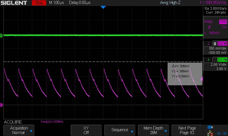
STM32F446 ADCs Fighting Inputs
Posted on March 09, 2017 at 16:59
I am using a single channel on ADC1, and a single channel on ADC2, both using DMA. Everything code-wise is working, but the ADCs appear to be fighting/resisting the inputs. For instance, with nothing connected, each ADC pin floats at ~1V. But then when you try to ground either input through a 10K resistor, I get a ~250mV triangle wave at 1MHz. Image is attached below, along with CUBE generated ADC initialization code. Any ideas on what could be causing that? I would think that grounding an ADC input through a 10K would cause the input to go to zero.
[code]
static void MX_ADC1_Init(void)
{
ADC_ChannelConfTypeDef sConfig;
/**Configure the global features of the ADC (Clock, Resolution, Data Alignment and number of conversion)
*/
hadc1.Instance = ADC1;
hadc1.Init.ClockPrescaler = ADC_CLOCK_SYNC_PCLK_DIV6;
hadc1.Init.Resolution = ADC_RESOLUTION_12B;
hadc1.Init.ScanConvMode = ENABLE;
hadc1.Init.ContinuousConvMode = ENABLE;
hadc1.Init.DiscontinuousConvMode = DISABLE;
hadc1.Init.ExternalTrigConvEdge = ADC_EXTERNALTRIGCONVEDGE_NONE;
hadc1.Init.ExternalTrigConv = ADC_SOFTWARE_START;
hadc1.Init.DataAlign = ADC_DATAALIGN_RIGHT;
hadc1.Init.NbrOfConversion = 1;
hadc1.Init.DMAContinuousRequests = ENABLE;
hadc1.Init.EOCSelection = ADC_EOC_SEQ_CONV;
if (HAL_ADC_Init(&hadc1) != HAL_OK)
{
Error_Handler();
}
/**Configure for the selected ADC regular channel its corresponding rank in the sequencer and its sample time.
*/
sConfig.Channel = ADC_CHANNEL_0;
sConfig.Rank = 1;
sConfig.SamplingTime = ADC_SAMPLETIME_3CYCLES;
//sConfig.SamplingTime = ADC_SAMPLETIME_480CYCLES;
if (HAL_ADC_ConfigChannel(&hadc1, &sConfig) != HAL_OK)
{
Error_Handler();
}
}
/* ADC2 init function */
static void MX_ADC2_Init(void)
{
ADC_ChannelConfTypeDef sConfig;
/**Configure the global features of the ADC (Clock, Resolution, Data Alignment and number of conversion)
*/
hadc2.Instance = ADC2;
hadc2.Init.ClockPrescaler = ADC_CLOCK_SYNC_PCLK_DIV6;
hadc2.Init.Resolution = ADC_RESOLUTION_12B;
hadc2.Init.ScanConvMode = ENABLE;
hadc2.Init.ContinuousConvMode = ENABLE;
hadc2.Init.DiscontinuousConvMode = DISABLE;
hadc2.Init.ExternalTrigConvEdge = ADC_EXTERNALTRIGCONVEDGE_NONE;
hadc2.Init.ExternalTrigConv = ADC_SOFTWARE_START;
hadc2.Init.DataAlign = ADC_DATAALIGN_RIGHT;
hadc2.Init.NbrOfConversion = 1;
hadc2.Init.DMAContinuousRequests = ENABLE;
hadc2.Init.EOCSelection = ADC_EOC_SEQ_CONV;
if (HAL_ADC_Init(&hadc2) != HAL_OK)
{
Error_Handler();
}
/**Configure for the selected ADC regular channel its corresponding rank in the sequencer and its sample time.
*/
sConfig.Channel = ADC_CHANNEL_1;
sConfig.Rank = 1;
//sConfig.SamplingTime = ADC_SAMPLETIME_480CYCLES;
sConfig.SamplingTime = ADC_SAMPLETIME_3CYCLES;
if (HAL_ADC_ConfigChannel(&hadc2, &sConfig) != HAL_OK)
{
Error_Handler();
}
}
[/code]