STM32F411RET6 Can't boot, a floating GPIO during startup.
STM32F411RET6 Can't boot, a floating GPIO during startup.
I am designing aى energy meter.
It has a "Capacitive power supply" so it is very limited power (16mA @ 16V), rise time for the voltage rail is in ms.
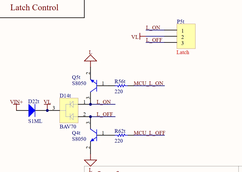
The meter has Latching relay. We are driving this latch through GPIO & npn as shown in the schematics pic.
My bad design, I didn't put a pull-down resistors in the latch control lines.
During startup the latch control (MCU_L_ON & MCU_L_OFF) are float, till the FW boots and set the GPIO to 0.
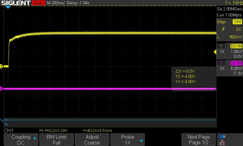
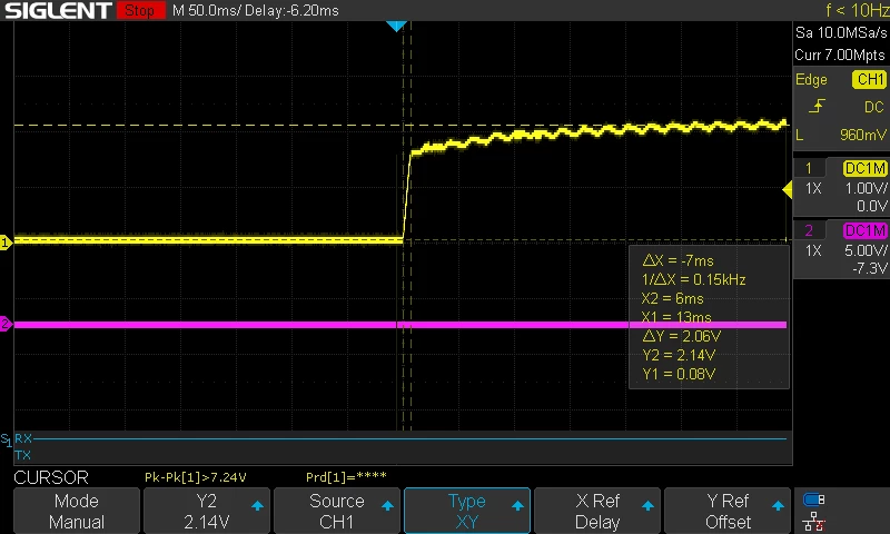
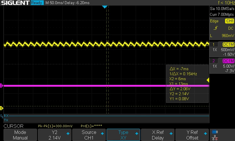
Out of 50 produced & flashed: 40 pcs success in booting. 10 didn't success. The failed ones has consistent behavior of having voltage of 0.6v on MCU_L_OFF which makes the npn turns ~ on and draws current, so the voltage in the power supply won't increase as it should. Vcc (3v3) voltage stays around 2.2v. it has small oscillations but never fall below 2v. If latch control disconnected, no issue occur.
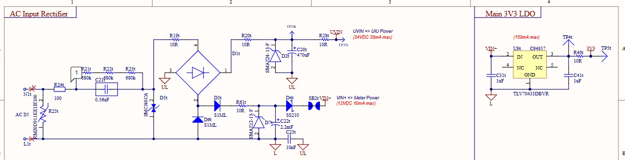
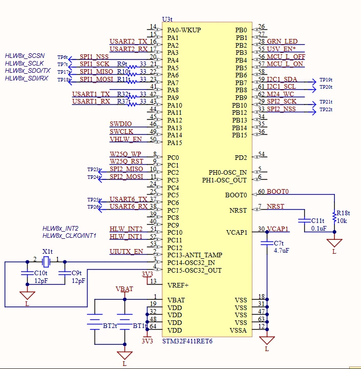
We don't have brown out enabled. Only the watchdog through configuration bytes with 0.5s default time.
The current booting sequence: GPIO initialized, Watchdog initialized, rest of the FW modules are initialized.
My questions are:
1- Why float GPIO pins during startup has this voltage continously?
2- Why some boards worked and others didn't with consistent behavior on each single board?
3- Why the MCU didn't boot, though the datasheet says it works from 1.8v. We have 2.2v with small oscillations.
4- In next release I added the pull-down, but how will solve it. We have 0.6v measured now. If we add a 10k pull-down, it will draw very small current to make any effect.
5- Is there any FW solution I can do to this batch to ensure it will boot for sure.