

LLOLO.1
Associate III
November 11, 2020
Question

STM32F405RG weird ADC spikes

  • November 11, 2020
  • 32 replies
  • 15087 views

Hi I am working on a small project where I need to sample couple of ADC channels.

I am using STM32F405RG. ADC1 is running in continuous and scan mode with DMA. I am using ping pong buffers to send ADC data through USART.

After gathering some data I plot them in MATLAB.

Problem is that there are random spikes in my ADC values an example is shown below.

X axis is Seconds, Y axis is voltage. Graph belongs to an ADC channel where approximately 2.6 volts needs to be read.
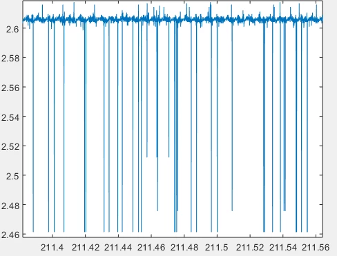
0693W000005B0hlQAC.png 

Has anyone encountered this ?

This topic has been closed for replies.

32 replies

Ozone
Principal
November 11, 2020

The scale is a bit out of proportion, albeit 150mV is not just noise.

What are your input parameters and ADC settings (input impedance, sampling time) ?

Is Vdda kept separate from Vdd, and properly filtered/stabilized ?

Have you tried to observe it (Vdda) simultaneously with the ADC values on a scope ?

waclawek.jan
Super User
November 11, 2020

This is most likely consequence of switching of the sampling capacitor.

JW

LLOLO.1
LLOLO.1Author
Associate III
November 11, 2020

Can 22kohms input impedance with switching cap cause this ?

LLOLO.1
LLOLO.1Author
Associate III
November 11, 2020

I set ADC input impedance according to reference manual formula which resulted in Rin = 22kohms. Overall sampling frequency is 200ksps so for 8 channels 25ksps/ch. There is ferrite bead between Vdda and Vcc and recommended capacitors between Vdda and ground. I measured both Vcc and Vdda they seem to be ok. I measured Vdda there are no voltage dipping when sampling.

Ozone
Principal
November 11, 2020

That does not sound correct to me.

The input must be capable of fully charging (or discharging) the S&H capacitor over the sum input impedance in the given sample time.

A simple RC network as first-order approximation.

I would expect a one order of magnitude smaller Rin.

LLOLO.1
LLOLO.1Author
Associate III
November 11, 2020

Well, APB2 Clock is 64Mhz divided by ADCPRE = 2 results in 32MHz. 28Clock cycle is selected and with 12 bit ADC total clock cycle is 40. 32Mhz/40 = 800kHz but I am triggering ADC with Timer which is set to 200kHz. I am calculating Rin according to set ADC values.

waclawek.jan
Super User
November 12, 2020

> 28Clock cycle is selected

The sampling capacitor is switched to input signal source for those 28 clock cycles, i.e. less than 1us. The signal source must be capable of fully charging that capacitor in that time.

If the above picture is output of ADC rather than voltage on the pin observed by oscilloscope, it still may be also other reasons mentioned by Ozone.

JW

LLOLO.1
LLOLO.1Author
Associate III
November 12, 2020

I have increased the sampling time to124 cycles and spikes still occur. I am confused.

Ozone
Principal
November 12, 2020

Is this data (the spikes) the collected ADC data ?

Have you tried lowering the impedance at the ADC input, perhaps trying another low-impedance voltage source ?

What data noise do you see if you connect the ADC input to ground (0 Volts) ?

waclawek.jan
Super User
November 12, 2020

Also, do you run other ADC or DAC?

JW

LLOLO.1
LLOLO.1Author
Associate III
November 12, 2020

Yes, the figure in my post was collected ADC data. I use only ADC other analog peripherals are disabled.

"Have you tried lowering the impedance at the ADC input, perhaps trying another low-impedance voltage source ?

What data noise do you see if you connect the ADC input to ground (0 Volts) ?"

I will try that.

LLOLO.1
LLOLO.1Author
Associate III
November 12, 2020

measuring ground gives ADC standard noise with spikes. Also I sampled single channel with scan mode, still there are spikes. I tried using another low impedance function generator as my signal source. There are still spikes

LLOLO.1
LLOLO.1Author
Associate III
November 13, 2020

Disabling scan mode didn't help.

gregstm
Senior II
November 12, 2020

Just some thoughts: try reading the Vrefint ADC channel. does your design have a ground plane? do you have 100nF surface mount caps at all VDD pins? (with minimal path between VDD pin, cap and ground plane). Does your CPU sleep while it waits for data/DMA/interrupts? - if so, try running without sleep (or other low powered mode) to see if spikes are caused by CPU demand surges. Can we see a schematic of your analog input section? What exactly are you measuring? Are any nearby computers using wifi?

LLOLO.1
LLOLO.1Author
Associate III
November 13, 2020

Yes design has ground plane. I have recommended capacitor configuration according to datasheet. Yes my CPU sleeps while waiting for DMA. I disabled the low power modes but the results didn't changed. There is nothing on my analog input. PA2 (ADC1 ch2) connected directly to external function generator. There is nothing in between. I don't think this problem is due to WiFi. I have only my phone in my pocket :\

gregstm
Senior II
November 13, 2020

Is it possible to keep the same set up and read the Vrefinternal channel? That is the internal voltage reference. Then try the same with not function generator connected. I assume your function generator is mains powered. I would try to design all tests to be disconnected from mains powered devices and to be battery powered (no switching power supplies anywhere - not even nearby. Test for interference: Get a portable AM radio and slightly off-tune it to a low frequency radio channel and see what is producing the most electromagnetic noise in your room)

tkor.1
Associate
November 12, 2020

Do you have spikes when you put input to ground ?
