

Question
STM32F405 - SPI MPU-6500
Hi,
I am trying to communicate with the MPU-6500 from InvenSense and the STM32F405 micro controller in SPI.I managed to read the WHO AM I. And seems to respond well with its value of 0x70.
The problem I have is when I want to read the accelerometer and gyroscope values I get random values.
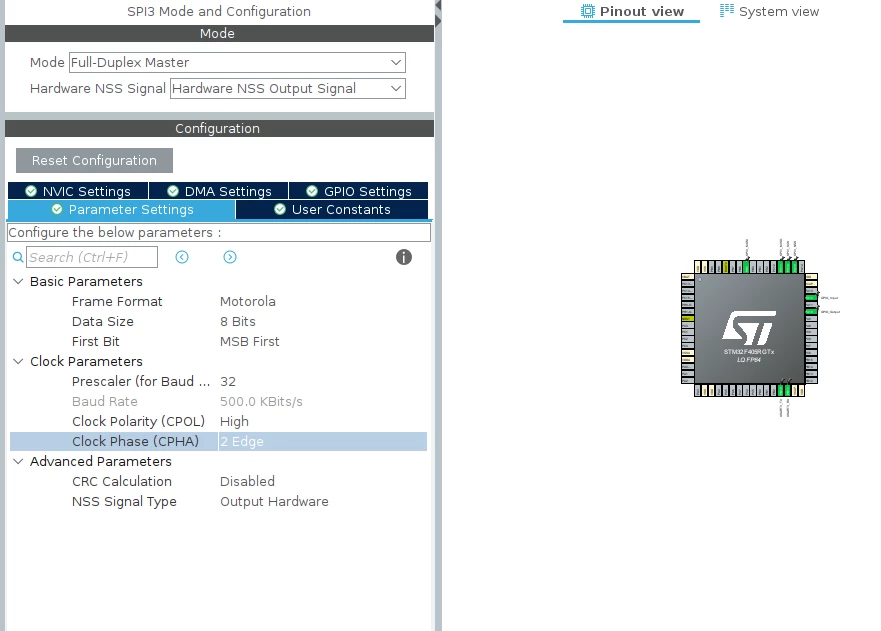
Here are the SPI configurations:
Prescale to 32 to have a baud rate of 500Kbit/s (Maximum frequecny at 1Mhz) / CPOL to High /Clock Phase: 2 Edge.
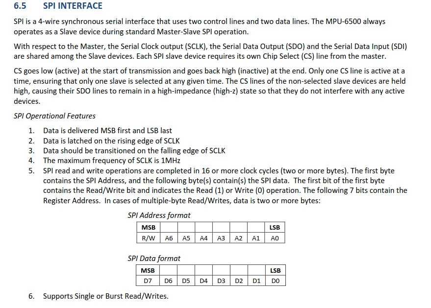
Here are the characteristics of the MPU6500 :
And finally here is the code that I have for these different operations :
/* Private function prototypes -----------------------------------------------*/
void SystemClock_Config(void);
static void MX_GPIO_Init(void);
static void MX_SPI3_Init(void);
static void MX_USART3_UART_Init(void);
/* USER CODE BEGIN PFP */

/* USER CODE END PFP */

/* Private user code ---------------------------------------------------------*/
/* USER CODE BEGIN 0 */
#define CS_SELECT 0
#define CS_DESELECT 1
#define READWRITE 0x80
#define SPI_TIMOUT_MS 1000
#define PWR_MGMT_1 0x6B
#define USER_CTRL 0x6A
#define CONFIG 		 0x1A
#define GYRO_CONFIG 0x1B
#define WHO_AM_I 0x75
#define WHO_AM_I_6500_ANS 0x70
#define ACCEL_XOUT_H 0x3B
#define GYRO_ZOUT_H 0x47
#define GYRO_ZOUT_L 0x48
#define ACCEL_XOUT_H	 0x3B
#define ACCEL_XOUT_L 0x3C
#define LP_ACCEL_ODR	 0x1E
#define SIGNAL_PATH_RESET 0x68

float GYRO_FACTOR=16.4;

#define TRUE 1
#define FALSE 0


uint8_t readByte(uint8_t reg)
{
 uint8_t rx_data[2];
 uint8_t tx_data[2];

 tx_data[0] = reg | 0x80;
 tx_data[1] = 0x00; // dummy

 HAL_SPI_TransmitReceive(&hspi3, tx_data, rx_data, 2, 1);

 return rx_data[1];
}

void writeByte(uint8_t reg, uint8_t data)
{
 uint8_t rx_data[2];
 uint8_t tx_data[2];

 tx_data[0] = reg & 0x7F;
 tx_data[1] = data; // write data

 HAL_SPI_TransmitReceive(&hspi3, tx_data, rx_data, 2, 1);

}

uint8_t MPU_begin()
{
 // Initialize variables
 uint8_t addr, val;
 uint8_t who_am_i = 0;

 // Confirm device
 who_am_i = readByte( WHO_AM_I );
 printf( "0x%x \n",who_am_i );
 if (who_am_i == WHO_AM_I_6500_ANS)
 {
 // Startup / reset the sensor
 addr = PWR_MGMT_1;
 val = 0x80;
 writeByte(addr,val);
 HAL_Delay(100);

 addr = SIGNAL_PATH_RESET;
 val = 0x07;
 // writeByte(addr,val);
 HAL_Delay(100);

 // Disable FSYNC
 addr = CONFIG;
 val = 0x00;
 writeByte(addr,val);
 HAL_Delay(50);

 //Config gyro 2000dps -> 2000dps : 16.4dps = 1deg/s
 addr = GYRO_CONFIG;
 val = 0x00;
 writeByte(addr,val);
 HAL_Delay(50);

 //Config freqence Acc
 addr = LP_ACCEL_ODR;
 val = 0x00;
 writeByte(addr,val);
 HAL_Delay(50);

 return 1;
 }
 else
 {
 return 0;
 }
}


/* USER CODE END 0 */

/**
 * @brief The application entry point.
 * @retval int
 */
int main(void)
{
 /* USER CODE BEGIN 1 */
	int16_t accel_x_value;
	int16_t accel_y_value;
	int16_t accel_z_value;
	float accel_x;
	float accel_y;
	float accel_z;

	int16_t gyro_x_value;
	int16_t gyro_y_value;
	int16_t gyro_z_value;
	float gyro_x_ang_vel;
	float gyro_y_ang_vel;
	float gyro_z_ang_vel;

	int16_t temp_value;
	float temp;
 /* USER CODE END 1 */

 /* MCU Configuration--------------------------------------------------------*/

 /* Reset of all peripherals, Initializes the Flash interface and the Systick. */
 HAL_Init();

 /* USER CODE BEGIN Init */

 /* USER CODE END Init */

 /* Configure the system clock */
 SystemClock_Config();

 /* USER CODE BEGIN SysInit */

 /* USER CODE END SysInit */

 /* Initialize all configured peripherals */
 MX_GPIO_Init();
 MX_SPI3_Init();
 MX_USART3_UART_Init();
 /* USER CODE BEGIN 2 */

 if (MPU_begin() != TRUE)
 {
 printf("ERROR SPI Communication!\r\n");
 while (1){}
 }else{
	 printf("MPU6500 - OK\n");
 }

 /* USER CODE END 2 */

 /* Infinite loop */
 /* USER CODE BEGIN WHILE */
 while (1)
 {
 /* USER CODE END WHILE */

 /* USER CODE BEGIN 3 */
	// ACCELEROMETER MEASUREMENT ACCEL_XOUT_H & ACCEL_XOUT_L
	accel_x_value = ( ((int16_t)readByte(0x3B)<<8) | ((int16_t)readByte(0x3C)&0x00ff) );
	accel_x = (float)accel_x_value / 16384;
	printf("ACCEL_XOUT = %6d[Raw] = %6.3lf[g]\n\r", accel_x_value, accel_x);

	// ACCELEROMETER MEASUREMENT ACCEL_YOUT_H & ACCEL_YOUT_L
	accel_y_value = ( ((int16_t)readByte(0x3D)<<8) | ((int16_t)readByte(0x3E)&0x00ff) );
	accel_y = (float)accel_y_value / 16384;
	printf("ACCEL_YOUT = %6d[Raw] = %6.3lf[g]\n\r", accel_y_value, accel_y);

	// ACCELEROMETER MEASUREMENT ACCEL_ZOUT_H & ACCEL_ZOUT_L
	accel_z_value = ( ((int16_t)readByte(0x3F)<<8) | ((int16_t)readByte(0x40)&0x00ff) );
	accel_z = (float)accel_z_value / 16384;
	printf("ACCEL_ZOUT = %6d[Raw] = %6.3lf[g]\n\r", accel_z_value, accel_z);

	// GYROSCOPE MEASUREMENT GYRO_XOUT_H & GYRO_XOUT_L
	gyro_x_value = ( ((int16_t)readByte(0x43)<<8) | ((int16_t)readByte(0x44)&0x00ff) );
	gyro_x_ang_vel = (float)gyro_x_value / 131;
	printf(" GYRO_XOUT = %5d[Raw] = %8.3lf[deg/s]\n\r", gyro_x_value, gyro_x_ang_vel);

	// GYROSCOPE MEASUREMENT GYRO_YOUT_H & GYRO_YOUT_L
	gyro_y_value = ( ((int16_t)readByte(0x45)<<8) | ((int16_t)readByte(0x46)&0x00ff) );
	gyro_y_ang_vel = (float)gyro_y_value / 131;
	printf(" GYRO_YOUT = %5d[Raw] = %8.3lf[deg/s]\n\r", gyro_y_value, gyro_y_ang_vel);

	// GYROSCOPE MEASUREMENT GYRO_ZOUT_H & GYRO_ZOUT_L
	gyro_z_value = ( ((int16_t)readByte(0x47)<<8) | ((int16_t)readByte(0x48)&0x00ff) );
	gyro_z_ang_vel = (float)gyro_z_value / 131;
	printf(" GYRO_ZOUT = %5d[Raw] = %8.3lf[deg/s]\n\r", gyro_z_value, gyro_z_ang_vel);

	// TEMPERATURE MEASUREMENT GYRO_ZOUT_H & GYRO_ZOUT_L
	temp_value = ( ((int16_t)readByte(0x41)<<8) | ((int16_t)readByte(0x42)&0x00ff) );
	temp = (float)temp_value / 326.8 + 25.0;
	printf(" TEMP_OUT = %5d[Raw] = %3.1lf[℃]\n\r", temp_value, temp);

	HAL_Delay(10);
 }
 /* USER CODE END 3 */
}
Do you know why I have these random values? Thanks in advance
Sincerely
