Associate
Dec 17, 2025 5:35 PM UTC
Solved

STM32F4 with DCMI

Hello, we have device with very old TFT display which is dying. New one is unable to obtain. It has similar interface as DCMI: vsync, hsync, pixclk, D0-D8.

I have connected these clock/data lines to DCMI port, but interrupts was not triggered.

Here are my clock lines (from top: vsync, hsync, pix):

Screenshot 2025-12-17 182625.png

I suspect that timing of clock signals is not correct - compared with image I have found:
DCMI.png

clock signal is continuous, hsync/vsync falling at the same time... Can somebody confirm this, or can somebody point me to document with detailed dcmi clock format/timing?

Thank you.
mm

KDJEM.1
KDJEM.1Best answer
ST Technical Moderator
Dec 19, 2025 10:29 AM UTC

Hello @mm10 and welcome to the community;


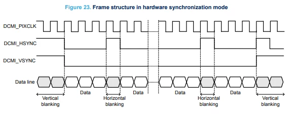
Figure 23. in AN5020 shows an example of data transfer when DCMI_VSYNC and DCMI_HSYNC are active high, and when the capture edge for DCMI_PIXCLK is the rising edge.

You need to make sure that DCMI_HSYNC and DCMI_VSYNC polarities are programmed according to the
camera module configuration. In the hardware synchronization mode (ESS = 0 in DCMI_CR), the IT_VSYNC
interrupt is generated (if enabled), even when CAPTURE = 0 in DCMI_CR. 

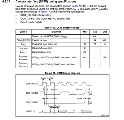
For more details about the DCMI clock timing, I recommend you to look at STM32F4 datasheet.

If you use STM32F437, you can refer to DS9484

KDJEM1_0-1766140025875.png

I propose to disable all other sources and keep only the DCMI interrupts (or you can set the DCMI at the high priority level) to check if the problem is resolved.


I hope this help you. 

Thank you.

Kaouthar

To give better visibility on the answered topics, please click on "Best answer" on the reply which solved your issue or answered your question.

2 replies

KDJEM.1
KDJEM.1Best answer
ST Technical Moderator
Dec 19, 2025 10:29 AM UTC

Hello @mm10 and welcome to the community;


Figure 23. in AN5020 shows an example of data transfer when DCMI_VSYNC and DCMI_HSYNC are active high, and when the capture edge for DCMI_PIXCLK is the rising edge.

You need to make sure that DCMI_HSYNC and DCMI_VSYNC polarities are programmed according to the
camera module configuration. In the hardware synchronization mode (ESS = 0 in DCMI_CR), the IT_VSYNC
interrupt is generated (if enabled), even when CAPTURE = 0 in DCMI_CR. 

For more details about the DCMI clock timing, I recommend you to look at STM32F4 datasheet.

If you use STM32F437, you can refer to DS9484

KDJEM1_0-1766140025875.png

I propose to disable all other sources and keep only the DCMI interrupts (or you can set the DCMI at the high priority level) to check if the problem is resolved.


I hope this help you. 

Thank you.

Kaouthar

To give better visibility on the answered topics, please click on "Best answer" on the reply which solved your issue or answered your question.
mm10Author
Associate
Dec 23, 2025 7:52 AM UTC

Thank you for reply. I'm using stm32f429-disco which share DCMI pins with other devices and it seems it's not suitable for me anyhow because vsync/hsync pin can not be remap (no DCMI + display in the same time). I will need to get another board just with mcu+sdram to test it. In the meantime I got success with timers+DMA.