

STM32F4 DMA Request Mapping Table & TIM1/TIM8 confusion
Using the STM32F446RE with very good results so far including ADC1,ADC2,ADC3 DMA to SRAM arrays. ADCs and DMA (peripheral to memory) were fairly easy but the TIMER 1 and TIMER 8 PWM usage is giving me some problems in understanding how DMA and the Advanced timers work. I may have to move one or two of my ADC DMA Streams/Channels but that's OK as long as the other choices will allow what I need.
I have been working on getting tables periodically loaded into two (2) TIM1 and TIM8 Capture Compare Registers (CCR1 & CCR2 or CCR3)) using DMA . Four (4) output pins from each timer for each corner of a full wave bridge circuit. Negated and Non-Negated CCR PWM outputs are working good (also Dead Time) using a fixed timer interrupt to stuff the waveform table values into the CCRs but this really needs to be done from DMA waveform tables and triggered using ITR0-ITR4 methods using Timer 2, 3, 4 or 5.
But I am confused with some of the terms used in the DMA2 mapping table. I have searched quite a bit and found hints in example code and documentation but am now needing to post questions because nobody, it would appear, is doing what I am trying to do. I am attaching a pic of the DMA2 table here for quick reference.
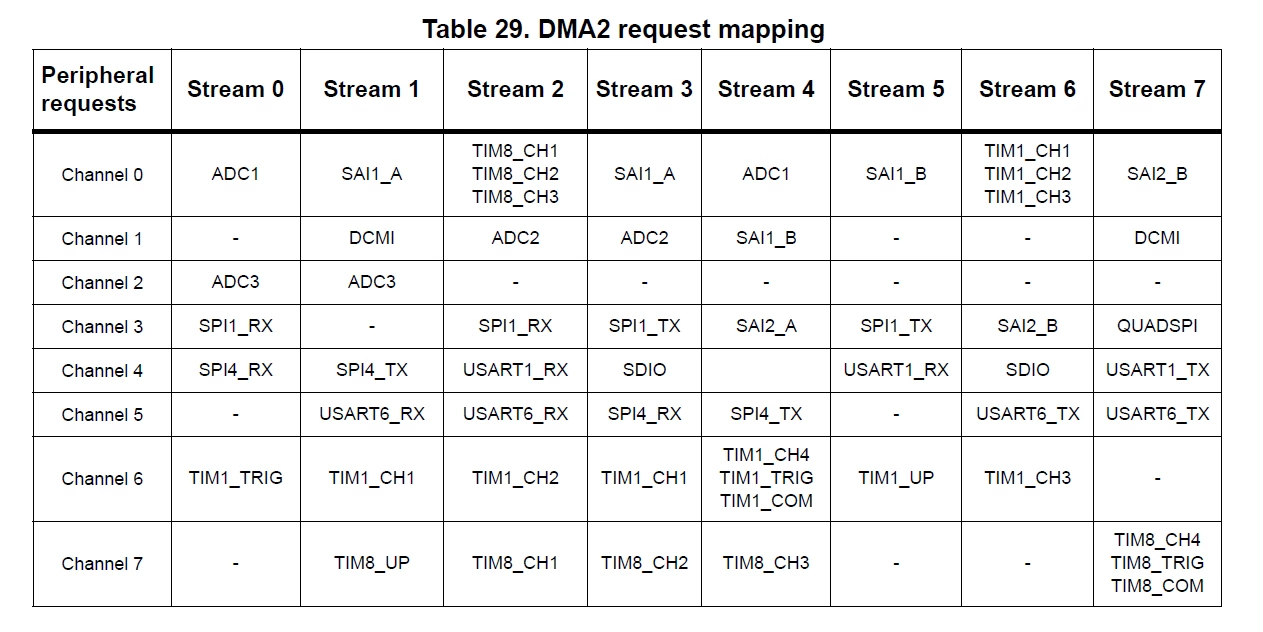
Stream 2 Channel 0 shows three Timer 8 CCRs I'm pretty sure....
TIM8_CH1
TIM8_CH2
TIM8_CH3
Same with Stream 6 Channel 0 for TIMER 1 and CH1, CH2, CH3.
Which one(s) is it ? Is it all three at the same time with one waveform indexed table value or can CH1 be updated with the first waveform table's indexed value, CH2 with the next value and CH3 with the 3rd table value or are they all the same value being sent to all 3 Channels ?
To be useful for 3 phase PWM, I believe all 3 channels would need to be updated with a different value from a different table (different source addresses) or one waveform table with interleaved values, 1,2,3,1,2,3,1,2,3 etc. There is only one source address so it must be interleaved I am guessing. Memory to Peripheral of course.
The Advanced Timer chapters don't seem to address this in a way I can understand either.
Then there is Stream 4, Channel 6 showing 3 different uses...
TIM1_CH4
TIM1_TRIG
TIM1_COM
What and/or how are these 3 used ? TIM1_CH4 is most likely CCR4, Not exactly sure about TIM1_TRIG (must be Timer 1 Trigger but how ?), and I do not find much about what exactly TIM1_COM means. Is it COM for COMmunications ? COMMUTATE ?
Same thing for Stream 7 Channel 7 for TIM8.
One more... Stream 1 Channel 7 is TIM8_UP and Stream5 Channel 6 TIM1_UP....
Is this UP for UPDATE ? UP for UP count ? Can't exactly tell. One sentence on these would most likely clear up my confusion on these terms.
Any and all help with describing these or pointing to some documentation or better examples are MUCH appreciated !
Thank you SO much !
boB
