dbingle
Associate
July 10, 2013
Question

STM32f207 remapping pins problem

  • July 10, 2013
  • 20 replies
  • 3581 views
Posted on July 10, 2013 at 17:17

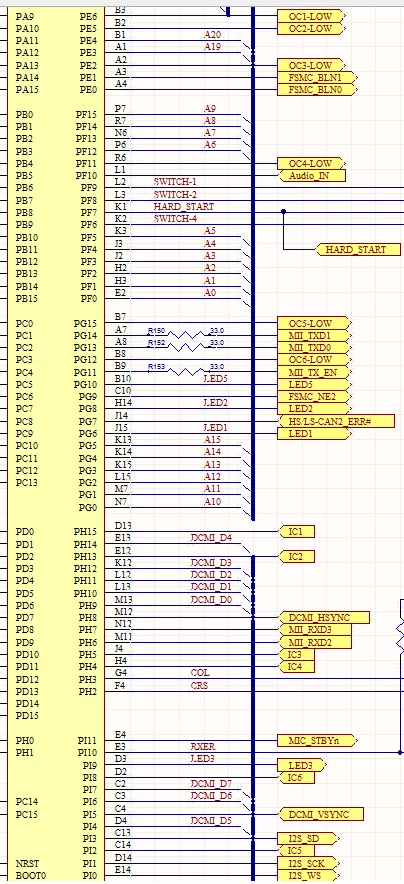
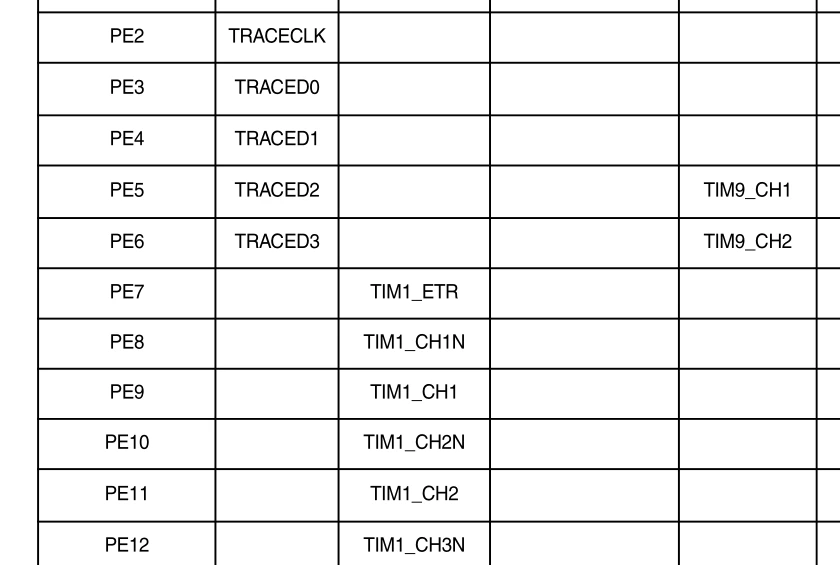
I'm not sure how to remap pins that do not line up correctly with the alternate functions specified in the datasheet. For example, the picture below shows the pin out of my microcontroller where OCx-LOW are pwm out and ICx are pwm in. Comparing it to the datasheet's alternate function listing, only some pins line up to timer channels. For example, OC1-LOW and OC2-LOW pin's alternate functions match up to timer 9 channel 2 and 1, but OC3-LOW and OC4-LOW don't match up to any timers on their alternate functions so I'm not sure how to use these pins with the timers for pwm out/in.

When they match, you can do something like the following, but not sure what to do when they don't line up.

GPIO_InitStructure.GPIO_Pin = GPIO_Pin_2;
GPIO_InitStructure.GPIO_Mode = GPIO_Mode_AF;
GPIO_InitStructure.GPIO_Speed = GPIO_Speed_100MHz;
GPIO_InitStructure.GPIO_OType = GPIO_OType_PP;
GPIO_InitStructure.GPIO_PuPd = GPIO_PuPd_NOPULL;
GPIO_Init(GPIOI, &GPIO_InitStructure); 
/* Connect pins to TIM8 AF2 */
GPIO_PinAFConfig(GPIOI, GPIO_PinSource2, GPIO_AF_TIM8);

0690X00000604woQAA.png 0690X00000604lDQAQ.png Sorry if it's a simple solution, I've never programmed any microcontroller before.
    This topic has been closed for replies.

    20 replies

    Tesla DeLorean
    Guru
    July 10, 2013
    Posted on July 10, 2013 at 17:31

    When they match, you can do something like the following, but not sure what to do when they don't line up.


    I guess you ask the board designer and review team what they were thinking? The AF muxing fabric has limited connectivity, it does not offer a crossbar-switch type functionality. So if it's not listed, it's not escaping on those pins.

    See if you have other free pins in your design where you can escape the signals you need, and add some trace wires to your board.

    TIM9 only has TWO channels.

    The other alternative is to program them as GPIO pins and drive them via software, providing the speed and placement are less critical.

    Tips, Buy me a coffee, or three.. PayPal Venmo (See Profile) Up vote any posts that you find helpful, it shows what's working..
    dbingle
    dbingleAuthor
    Associate
    July 10, 2013
    Posted on July 10, 2013 at 17:40

    What do you mean drive them as GPIO pins/how would you do that?  Someone suggested just having a timer run and poll it every let's say 1ms and then forward the polled signal/value to the pin, is that what you mean?  I've briefly tried doing this, but couldn't get it to work properly.

    Tesla DeLorean
    Guru
    July 10, 2013
    Posted on July 10, 2013 at 17:49

    Set them as GPIO outputs, and drive them high and low as required

      GPIO_InitStructure.GPIO_OType = GPIO_OType_PP;

      GPIO_InitStructure.GPIO_PuPd = GPIO_PuPd_NOPULL;

      GPIO_InitStructure.GPIO_Mode = GPIO_Mode_OUT;

      GPIO_InitStructure.GPIO_Pin = GPIO_Pin_5 | GPIO_Pin_6;

      GPIO_InitStructure.GPIO_Speed = GPIO_Speed_50MHz;

      GPIO_Init(GPIOE, &GPIO_InitStructure);

      GPIO_SetBits(GPIOE, GPIO_Pin_5 | GPIO_Pin_6);  // Both High

    Polling seems a bit sloppy, if you have a TIM unit generating CC1/2/3/4 interrupts when the events occur, you'd be micro second level accurate.

    Tips, Buy me a coffee, or three.. PayPal Venmo (See Profile) Up vote any posts that you find helpful, it shows what's working..
    dbingle
    dbingleAuthor
    Associate
    July 10, 2013
    Posted on July 10, 2013 at 17:53

    hmmm okay that makes sense, I'll give it a try and see what happens and post back with results.  Thanks for the help

    dbingle
    dbingleAuthor
    Associate
    July 10, 2013
    Posted on July 10, 2013 at 20:13

    So I tried this but always seems to yield a 50% duty cycle when I check the OC3-LOW pin with a scope and changing the timer channel 1 pulse does not affect it. Any ideas why this isn't working?

    static TIM_OCInitTypeDef TIM3_OC;
    void TIM_Init_Out(void) {
    TIM_TimeBaseInitTypeDef TIM_TimeBaseStructure;
    TIM_OCInitTypeDef TIM_OCInitStructure;
    GPIO_InitTypeDef GPIO_InitStructure;
    // Randomly chose timer 3 because it's not used elsewhere
    RCC_APB1PeriphClockCmd(RCC_APB1Periph_TIM3, ENABLE);
    // micro picture in first post, trying to get pwm-out on OC3-LOW, pin PE2
    RCC_AHB1PeriphClockCmd(RCC_AHB1Periph_GPIOE, ENABLE);
    // OC3-LOW on pin PE3
    GPIO_InitStructure.GPIO_Pin = GPIO_Pin_2;
    GPIO_InitStructure.GPIO_Mode = GPIO_Mode_OUT;
    GPIO_InitStructure.GPIO_Speed = GPIO_Speed_50MHz;
    GPIO_InitStructure.GPIO_OType = GPIO_OType_PP;
    GPIO_InitStructure.GPIO_PuPd = GPIO_PuPd_NOPULL;
    GPIO_Init(GPIOE, &GPIO_InitStructure);
    GPIO_SetBits(GPIOE, ~GPIO_Pin_2); //start bit low
     PrescalerValue = (uint16_t) ((SystemCoreClock) / MHZ_20) - 1;
    
    // setup timer
    TIM_TimeBaseStructure.TIM_Period = 665;
    TIM_TimeBaseStructure.TIM_Prescaler = PrescalerValue;
    TIM_TimeBaseStructure.TIM_ClockDivision = 0;
    TIM_TimeBaseStructure.TIM_CounterMode = TIM_CounterMode_Up;
    TIM_TimeBaseInit(TIM3, &TIM_TimeBaseStructure);
    // should give ~25% duty cycle
    TIM3_OC.TIM_OCMode = TIM_OCMode_PWM1;
    TIM3_OC.TIM_OutputState = TIM_OutputState_Enable;
    TIM3_OC.TIM_Pulse = 166;
    TIM3_OC.TIM_OCPolarity = TIM_OCPolarity_High; // interrupt on high signal? not sure
    TIM_OC1Init(TIM3, &TIM3_OC);
    TIM_OC1PreloadConfig(TIM3, TIM_OCPreload_Enable);
    TIM_ARRPreloadConfig(TIM3, ENABLE);
    // set up timer 3 interrupt
    NVIC_Setup(TIM3_IRQn, 0, ENABLE);
    TIM_ITConfig(TIM3, TIM_IT_CC1, ENABLE);
    /* TIM3 enable counter */
    TIM_Cmd(TIM3, ENABLE);
    }
    static int reverse=1;
    void TIM3_IRQHandler(void) {
    if (TIM_IT_CC1) {
    TIM_ClearFlag(TIM3, TIM_FLAG_CC1 | TIM_FLAG_CC2 | TIM_FLAG_CC3 | TIM_FLAG_CC4);
    if (reverse) {
    // first time through signal will be low, and interrupt was triggered from high edge so set
    // gpio pin high, and switch interrupt to low triggered
    TIM3_OC.TIM_OCPolarity = TIM_OCPolarity_Low;
    GPIO_ToggleBits(GPIOE, GPIO_Pin_2);
    reverse=0;
    } else {
    TIM3_OC.TIM_OCPolarity = TIM_OCPolarity_High;
    GPIO_ToggleBits(GPIOE, GPIO_Pin_2);
    reverse=1;
    }
    TIM_OC1Init(TIM3, &TIM3_OC);
    }
    }

    Tesla DeLorean
    Guru
    July 10, 2013
    Posted on July 10, 2013 at 21:36

    Any ideas why this isn't working?


    GPIO_SetBits(GPIOE, ~GPIO_Pin_2); // Don't think this works

    GPIO_ResetBits(GPIOE, GPIO_Pin_2); // Try this

    As for banging things up/down and getting the duty you want, I'd suggest you have the pin set high in the Update interrupt, and low when the CC1 hits. Honestly not sure you can catch the alternate edges in the manner you're attempting.
    Tips, Buy me a coffee, or three.. PayPal Venmo (See Profile) Up vote any posts that you find helpful, it shows what's working..
    dbingle
    dbingleAuthor
    Associate
    July 11, 2013
    Posted on July 11, 2013 at 15:05

    So if I understand that right, I should start the signal high. Have the CC1 interrupt set to low triggered and when triggered, set gpio bit low, and then at the next update event, set the gpio bit high - repeat?

    Is this setting the CC1 interrupt low triggered?

    TIM3_OC.TIM_OCPolarity = TIM_OCPolarity_Low;

    Also, how would I manage setting a frequency and duty cycle with this setup? I thought the timer update event was set every timer the counter hit overflow, so I'm not seeing how to trigger the update event and set the bits high at the appropriate frequency. EDIT: Okay I see that the CC1 interrupt is triggered when the counter matches the CCR1 register value. So the CC1 interrupt should trigger on the correct timing for the falling edge (assuming timer is reset to 0 for a starting point), but then the timer update and getting the right frequency is still throwing me off.
    dbingle
    dbingleAuthor
    Associate
    July 22, 2013
    Posted on July 22, 2013 at 18:12

    Still having trouble getting this to work. Trying another approach with no luck. This time around I initialize the gpio bit high and then on the CC1 interrupt, set the bit low, change the CCR1 value for the remaining cycles of a period and reset the timer. Then on the next interrupt, set the gpio bit high to mark one period.

    static int flip=1;
    void TIM3_IRQHandler(void){
    if ((TIM3->SR & TIM_IT_CC1) == TIM_IT_CC1) { 
    TIM_ClearITPendingBit(TIM3, TIM_IT_CC1);
    if (flip == 1) {
    GPIO_ResetBits(GPIOE, GPIO_Pin_2);
    TIM_OCInitStructure.TIM_Pulse = (TIM3->ARR)-(TIM3->CCR1);
    TIM_OC1Init(TIM3, &TIM_OCInitStructure);
    TIM_SetCounter(TIM3, 0);
    flip = 2;
    } else {
    GPIO_SetBits(GPIOE, GPIO_Pin_2);
    TIM_OCInitStructure.TIM_Pulse = 499; // static value for testing 499/665 period ~75% duty
    TIM_OC1Init(TIM3, &TIM_OCInitStructure);
    TIM_SetCounter(TIM3, 0);
    flip = 1;
    }
    }
    }

    The output I'm getting is strange when watching it with an oscilloscope. The duty cycle and frequency do not seem to have a direct correlation with how the pulse values are set within the TIM3_IRQHandler. Any suggestions?
    Tesla DeLorean
    Guru
    July 22, 2013
    Posted on July 22, 2013 at 21:27

    I can't get my head around what you're doing there.

    Here's how I'd generate a software PWM using TIM3 on an F4, the F2 should be directly portable.

    // STM32 PWM 30 KHz (TIM3 CH1 via PE2 by software) STM32F4 Discovery - sourcer32@gmail.com
    #include ''stm32f4_discovery.h''
    /**************************************************************************************/
    void RCC_Configuration(void)
    {
    /* --------------------------- System Clocks Configuration -----------------*/
    /* TIM3 clock enable */
    RCC_APB1PeriphClockCmd(RCC_APB1Periph_TIM3, ENABLE);
    /* GPIOE clock enable */
    RCC_AHB1PeriphClockCmd(RCC_AHB1Periph_GPIOE, ENABLE);
    }
    /**************************************************************************************/
    void GPIO_Configuration(void)
    {
    GPIO_InitTypeDef GPIO_InitStructure;
    /*-------------------------- GPIO Configuration ----------------------------*/
    GPIO_InitStructure.GPIO_Pin = GPIO_Pin_2;
    GPIO_InitStructure.GPIO_Mode = GPIO_Mode_OUT;
    GPIO_InitStructure.GPIO_OType = GPIO_OType_PP;
    GPIO_InitStructure.GPIO_PuPd = GPIO_PuPd_NOPULL;
    GPIO_InitStructure.GPIO_Speed = GPIO_Speed_100MHz;
    GPIO_Init(GPIOE, &GPIO_InitStructure);
    GPIO_ResetBits(GPIOE, GPIO_Pin_2);
    }
    /**************************************************************************************/
    void NVIC_Configuration(void)
    {
    NVIC_InitTypeDef NVIC_InitStructure;
    NVIC_InitStructure.NVIC_IRQChannel = TIM3_IRQn;
    NVIC_InitStructure.NVIC_IRQChannelPreemptionPriority = 0;
    NVIC_InitStructure.NVIC_IRQChannelSubPriority = 0;
    NVIC_InitStructure.NVIC_IRQChannelCmd = ENABLE;
    NVIC_Init(&NVIC_InitStructure);
    }
    /**************************************************************************************/
    void TIM3_IRQHandler(void)
    {
    if (TIM_GetITStatus(TIM3, TIM_IT_Update) != RESET)
    {
    TIM_ClearITPendingBit(TIM3, TIM_IT_Update);
    GPIO_SetBits(GPIOE, GPIO_Pin_2); // Set high at beginning of period
    }
    if (TIM_GetITStatus(TIM3, TIM_IT_CC1) != RESET)
    {
    TIM_ClearITPendingBit(TIM3, TIM_IT_CC1);
    GPIO_ResetBits(GPIOE, GPIO_Pin_2); // Set low when width count hit
    }
    }
    /**************************************************************************************/
    void TIM3_Configuration(void)
    {
    TIM_OCInitTypeDef TIM_OCInitStructure;
    TIM_TimeBaseInitTypeDef TIM_TimeBaseStructure;
    uint16_t Period, Prescaler;
    #if 1 
    Prescaler = ((SystemCoreClock / 2) / 20000000); // Timebase ticks at 20 MHz
    Period = 666; // ~30030 Hz, from 20000000/30030
    #else
    Prescaler = 0;
    Period = ((SystemCoreClock / 2) / 30000); // Period for 30 KHz frequency
    #endif
    /* Time base configuration */
    TIM_TimeBaseStructure.TIM_Prescaler = Prescaler - 1;
    TIM_TimeBaseStructure.TIM_Period = Period - 1;
    TIM_TimeBaseStructure.TIM_ClockDivision = 0;
    TIM_TimeBaseStructure.TIM_CounterMode = TIM_CounterMode_Up;
    TIM_TimeBaseInit(TIM3, &TIM_TimeBaseStructure);
    /* Enable TIM3 Preload register on ARR */
    TIM_ARRPreloadConfig(TIM3, ENABLE);
    /* TIM PWM1 Mode configuration */
    TIM_OCInitStructure.TIM_OCMode = TIM_OCMode_PWM1;
    TIM_OCInitStructure.TIM_OutputState = TIM_OutputState_Disable; // Don't need pin output, just interrupt
    TIM_OCInitStructure.TIM_Pulse = Period / 4; // 25%
    TIM_OCInitStructure.TIM_OCPolarity = TIM_OCPolarity_High; // Unrelated to interrupt
    /* Output Compare PWM1 Mode configuration: Channel 1 */
    TIM_OC1Init(TIM3, &TIM_OCInitStructure);
    TIM_OC1PreloadConfig(TIM3, TIM_OCPreload_Enable);
    /* TIM3 enable counter */
    TIM_Cmd(TIM3, ENABLE);
    TIM_ITConfig(TIM3, TIM_IT_Update, ENABLE);
    TIM_ITConfig(TIM3, TIM_IT_CC1, ENABLE);
    }
    /**************************************************************************************/
    int main(void)
    {
    RCC_Configuration();
    NVIC_Configuration();
    GPIO_Configuration();
    TIM3_Configuration();
    while(1); // Don't want to exit
    }

    Tips, Buy me a coffee, or three.. PayPal Venmo (See Profile) Up vote any posts that you find helpful, it shows what's working..
    dbingle
    dbingleAuthor
    Associate
    July 23, 2013
    Posted on July 23, 2013 at 17:54

    You're a lifesaver.  This worked out perfectly.  Only note is that setting TIM_Prescaler = Prescaler - 1 will go to max 66535 value if prescaler is 0.  Just setting TIM_Prescaler = 0 fixes the issue in that case.