HSaee.1
Associate
July 1, 2020
Question

stm32f103c8t6 short cuts after programming!

  • July 1, 2020
  • 19 replies
  • 8265 views

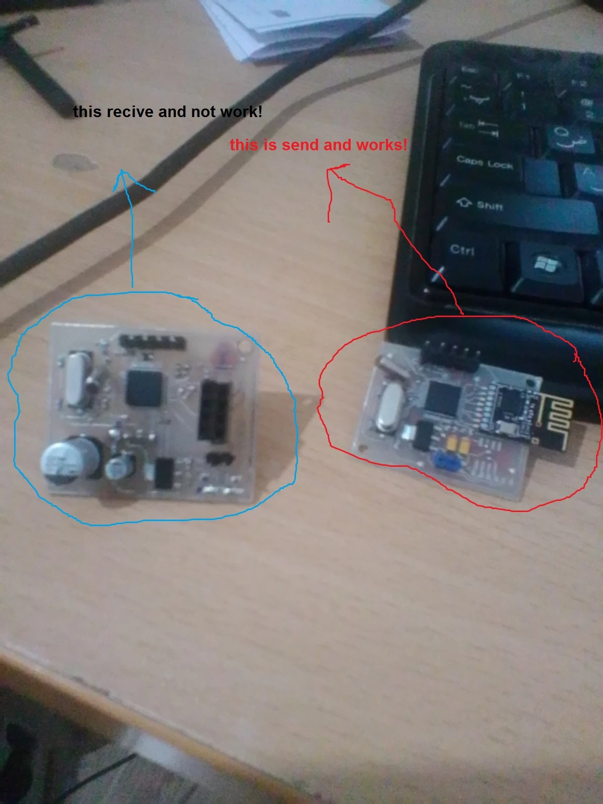
Hi, I am trying to make a circuit with stm32f103c8t6 and a nrf24l0+. I attach my schematic if pcb layout needed tell me to upload that. One of the circuit work good ( the send one) the other one which is identical does not.

after soldering I did check if any short cuts happen there was not any short cut, everything was good but after I power it up and connect the stlink_v2 and programming it ( it did it just fine) I tried to work with but it act abnormal

(especially timings) after I check for vcc and gnd pin I get 124 ohm or lower impedance on them I did it with other PCBs too but same thing happens.

My regulator , regulate voltage on 3.3 volt.

st_link_v2 work I could even program this 124 ohm stm32f103c8t6.

In other PCBs impedance reduce to 20 ohm.

The files are for altium designer .

send works but revive act abnormal .
0693W000001rxWVQAY.jpg

This topic has been closed for replies.

19 replies

TDK
July 1, 2020

The schematic looks fine to me. If impedance between 3.3V and GND dropped from ~10kOhm before to 124Ohm or 20ohm after programming, definitely indicates an issue. Make sure rails are stable, especially on powerup. Check for solder bridges.

Do you know what is causing the low impedance?

"If you feel a post has answered your question, please click ""Accept as Solution""."
HSaee.1
HSaee.1Author
Associate
July 2, 2020

Hi, before I power it up after soldering I checked for bridges and impedance of it was 1.88k ohm but after I power it up and connect to it the impedance drop to 120 ohm.

And interesting thing is that when I leave it (for 24 hour ) the impedance get back to the 1.88K ohm but again when I power it up and wait for some second and cut the power and measure the impedance it show 120 ohm again.

Is it possible that my electrolyte capacitor get to the problem when I was solder them? because time change the impedance and the voltage drop it.

THANK YOU FOR YOUR RESPOND;)

TDK
July 2, 2020

> Is it possible that my electrolyte capacitor get to the problem when I was solder them

That is one possibility. See if it gets hot while powered, or unsolder it and re-check.

"If you feel a post has answered your question, please click ""Accept as Solution""."
HSaee.1
HSaee.1Author
Associate
July 5, 2020

Hi, I did change the cap but it did not work!

I soldered another stm32f103c8t6 board exactly same things happened there was not any short circuit and impedance was good.

After I program the mcu it shows the short circuit and it could not connect to st_link any more!

In all my design I do not have that 1M ohm resistor on the crystal and maybe it is because of that!

I am confused I really do not know what should I do!

HSaee.1
HSaee.1Author
Associate
July 5, 2020

:|

Piranha
Principal III
July 5, 2020

3,3 V / 124 ohm = 27 mA ... seems to be normal working current. But 20 ohm is the approximate impedance of an output pin - probably software+hardware problem. What is the situation while keeping the NRST low (Reset button pressed)?

HSaee.1
HSaee.1Author
Associate
July 6, 2020

Hi , my problem is not impedance , now I have 50 ohm impedance but in this impedance the mcu could not connect to st_link or it connect (in higher impedance time change it)!but could not program and say protection mode is enable ( i did not enable it before!) and some time get program but hang during the short period of time. only different thing between the boards that works ( send is work! and my other board) and the one that's not work is this impedance.

first i did power up the mcu with st_link and then think maybe it could not give me that 27mA or more current because of that I connect it to better source (it could give 5A linear output) it programmed but mcu hanged after some time!

it's make no different when I push the reset button but in one case it's drop the current that mcu take from source. ( when it hang no different i should wait!)

Interesting thing is that when mcu hang I could not inter programming mode ( I mean connect to it and in here impedance is 120 ohm) but after some time ( after cutting the power) the impedance return to its 1k or more and then I could connect to it.

Make long story short the only strange thing I could see is impedance!

excuse me for writing much I want to describe all the situation.:\

TDK
July 5, 2020

You're not making the measurement while the chip is powered, are you? How exactly are you making the measurement?

"If you feel a post has answered your question, please click ""Accept as Solution""."
HSaee.1
HSaee.1Author
Associate
July 6, 2020

Hi , of course I cut the power ( base on Tevenan and Norton ( I do not know the right dictation ) that rule for calculating the

equivalent resistor and voltage ...).

And I do the measurement with my multi-meter.

HSaee.1
HSaee.1Author
Associate
July 16, 2020

Hi, again I did the design for stm32f030k6t6 in this case after some time it hang and it does not work after several programing I could not even erase it .

sth should wrong with my design but I could not figure it out I attach my schematic.0693W000001t3pkQAA.png0693W000001t3paQAA.png

HSaee.1
HSaee.1Author
Associate
July 16, 2020

there is same problem with stm32f103c8t6 I get the new pcb and MCU but again same problem short circuit!

someone PLEASE help me!0693W000001t3qxQAA.png0693W000001t3qsQAA.png0693W000001t3qnQAA.png

Piranha
Principal III
July 22, 2020

Another idea - probably all of these are consequences of using low-power modes, not configuring DBGMCU_CR and not using "connect under reset" on a debugger.

HSaee.1
HSaee.1Author
Associate
July 25, 2020

Hi , again I program my MCU under reset mode but for DBGMCU_CR I am not sure even I know what is that I will read about and report in here.

But yes the under reset programming was a problem before but not now I did have problem with that too but in other project that I learn about alot.

THANK YOU FOR RESPOND

HSaee.1
HSaee.1Author
Associate
November 24, 2020

Hi, I found the problem It was about footprint.

I downloaded a footprint from snapeda which was not approved ​and it got square pads.

In square pads sharp edge will be a problem and especially when frequency get higher and higher l. In 72MHz stm32 enter some situation to protect ic from this and show short circuit on it's power rail.

I replace footprint with a footprint which contain round pads and no more short circuit.

I almost change every thing in pcb the chip the solder and way of soldering nothing work except changing footprint.​

HSaee.1
HSaee.1Author
Associate
February 3, 2022

I know it is long time ago but I could find my problem and fix them.

--First thing that is IMPORTANT is to use foot print with round and longer pad it could help you to solder the MCU better and easier.

--Second THING do not afraid high temperature put the iron on 400c or 380c and make sure you use good solder wire (It should melts in lower degrees) for avoiding heat damage to MCU do not keep iron more than a second on a pad if it did not soldered do the process again but do not keep it on MCU pin for long period of time. the purpose of 380c and 400c is that in the temperature on the tip of the iron is less than that number on screen and tip it self have some resistance again heat transformation and pcb itself will absorbs the heat all of this will cause

the COLD JUNCTION (which was my problem) and it will be pain.

--At last Use the flux ( that oil thing helping to solder to stick to pad) and carefully clean it after you done. and make sure all the pin (specifically GND and VCC) are connected .