


Ayoub Cheggari
Senior
June 18, 2026
Solved

[STM32C011J4-SO8N] Clock Jitter

  • June 18, 2026
  • 3 replies
  • 96 views

Hello,


MCU : STM32C011J4-SO8N

Board : Custom


I am working on a Teleruptor and one of the feature is to control relay based on zero crossing due to relay latency.

My test code is simple:


while(1){    
if(HAL_GPIO_ReadPin(ZERO_CROSSING_GPIO_Port, ZERO_CROSSING_Pin) == GPIO_PIN_SET)
{
RELAY_CTRL_GPIO_Port->BSRR = RELAY_CTRL_Pin;
}
else
{
RELAY_CTRL_GPIO_Port->BRR = RELAY_CTRL_Pin;
}
}

I run my system at 3Mhz (Consumption matter) and I see a big clock jitter of (8-10us). Please see image below.
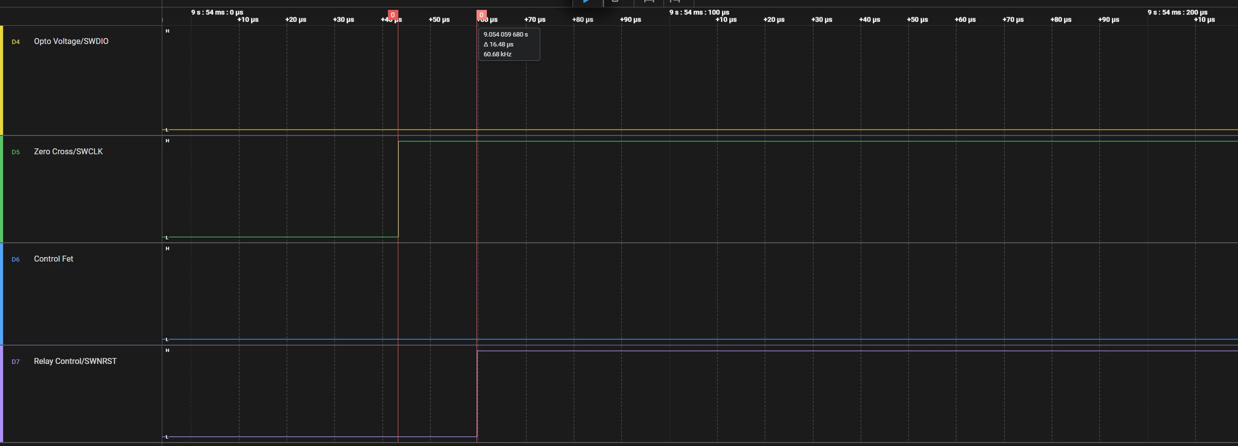
Normally, this shouldn’t take more than 1-2us.

I tried using EXTI but got the same issue.

I tried to run system at 12Mhz and issue is resolved but I can’t.


Question:

Is this behavior normal at this speed?

Is there any way I can reduce the jitter? 


Thanks,

Ayoub

Best answer by mƎALLEm

Better to check again what are the instructions involved in between the two rising edges (between the check of the input and the setting the GPIO output). 

PS: “jitter” is not the correct word in this case. Jitter is variations around an expected constant value. But here you mean more an “unexpected” delay value between a reading/checking and setting an IO.

3 replies

mƎALLEm
ST Technical Moderator
June 18, 2026

Hello,

“Normally, this shouldn’t take more than 1-2us.”

How did you estimate that?

You are using HAL which induce more delay due to the APIs overhead..

Did you check the assembly code and calculate that duration based on the frequency used and the instruction cycles’ number  : https://developer.arm.com/documentation/ddi0484/c/Programmers-Model/Instruction-set-summary

To give better visibility on the answered topics, please click "Best answer" on the reply which solved your issue or answered your question.
Ayoub Cheggari
Senior
June 18, 2026

Thanks for your comment!

Yes, I made an estimation.

At 3Mhz, each 1 cycle = 333ns 

I made a conversion of the lines into assembly and I got arround 10 cycles so 10*333ns = 3.3 us which faaar from 

10us I got.

mƎALLEm
mƎALLEmBest answer
ST Technical Moderator
June 18, 2026

Better to check again what are the instructions involved in between the two rising edges (between the check of the input and the setting the GPIO output). 

PS: “jitter” is not the correct word in this case. Jitter is variations around an expected constant value. But here you mean more an “unexpected” delay value between a reading/checking and setting an IO.

To give better visibility on the answered topics, please click "Best answer" on the reply which solved your issue or answered your question.