

dodonny
Associate III
January 6, 2021
Solved

STM32 won't start without physical reset.

  • January 6, 2021
  • 19 replies
  • 7558 views

Hi,

My mcu is STM32L476RGTx and I experiencing very strange behaviors to make my cpu start.

This mcu is on pcb I designed myself.

My boot0 pin is shorted to GND

And the reset pin pulled up to VCC.

I can program my chip with my st link (updated to the last version) an after each programming my chip is starting up as expected.

But as soon as I tried to make it boot from cold start it won't start. I have to manually press reset button and after that, it run as expected.

It append what ever i use as supply. 3V3 from programmer, 3V3 from local switching supply (LM43602)...

For the moment i do not use the 8mhz quartz on board.

Have you any idea I did not check yet or they're is any parameter that could prevent my mcu to run my program from flash but make it run as soon as I create a true reset event ?

Maybe is it BOD ? But how could I check that ?

anyway, Thanks for your help.
This topic has been closed for replies.
Best answer by dodonny

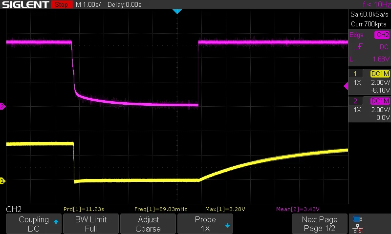
I put a 100uF capacitor between NRST and GND. Take 5 sc to charge. And boot fine with that !

(take care to the base time on the image below. Screen width take 14sc).

Same connection as previous. Top is VSS and bottom is NRST

0693W000006IAZLQA4.pngEDIT: Removed the 100uF capacitor (was only for testing) an removed the 100nF capacitor between NRST and GND and work fine now...

So i'll let it like that.

That was my 100nF capacitor (between NRST and GND) which is the faulty one. Was here to protect RESET button and debonce NRST signal. But seems too big.

19 replies

dodonny
dodonnyAuthor
Associate III
January 11, 2021

Here is a typical power up voltage trace. On top (RED one) you have the VDD signal and the bottom the RST signal voltage. Still not booting.

0693W000006I9luQAC.png

dodonny
dodonnyAuthor
Associate III
January 11, 2021

But if the ST-link is connected to the board and connected to usb (but without any software launched). The firmware start alone.

So make a cold start, and after connected the debugger -> the firmware not start. And this is the state, still in the boot loader zone :

> stm32l4x.cpu curstate
running
> halt
target halted due to debug-request, current mode: Thread
xPSR: 0xa1005800 pc: 0x1fff495e msp: 0x200030a8
> reg
===== arm v7m registers
(0) r0 (/32): 0x48000000
(1) r1 (/32): 0x89800000
(2) r2 (/32): 0x00010100
(3) r3 (/32): 0x50000b00
(4) r4 (/32): 0x200007d8
(5) r5 (/32): 0x48000400
(6) r6 (/32): 0x40021040
(7) r7 (/32): 0x48000000
(8) r8 (/32): 0x48000800
(9) r9 (/32): 0xe000e010
(10) r10 (/32): 0x40013000
(11) r11 (/32): 0x40003800
(12) r12 (/32): 0x00000000
(13) sp (/32): 0x200030a8
(14) lr (/32): 0x1fff4947
(15) pc (/32): 0x1fff495e
(16) xPSR (/32): 0xa1005800
(17) msp (/32): 0x200030a8
(18) psp (/32): 0x00000000
(20) primask (/1): 0x00
(21) basepri (/8): 0x00
(22) faultmask (/1): 0x00
(23) control (/3): 0x04
(24) d0 (/64): 0x0000000000000000
(25) d1 (/64): 0x0000000000000000
(26) d2 (/64): 0x0000000000000000
(27) d3 (/64): 0x0000000000000000
(28) d4 (/64): 0x0000000000000000
(29) d5 (/64): 0x0000000000000000
(30) d6 (/64): 0x0000000000000000
(31) d7 (/64): 0x0000000000000000
(32) d8 (/64): 0x0000000000000000
(33) d9 (/64): 0x0000000000000000
(34) d10 (/64): 0x0000000000000000
(35) d11 (/64): 0x0000000000000000
(36) d12 (/64): 0x0000000000000000
(37) d13 (/64): 0x0000000000000000
(38) d14 (/64): 0x0000000000000000
(39) d15 (/64): 0x0000000000000000
(40) fpscr (/32): 0x02000000
===== Cortex-M DWT registers

At the end, I will put a JMP in my boot loader zone to go 0x80000

XD

dodonny
dodonnyAuthorBest answer
Associate III
January 11, 2021

I put a 100uF capacitor between NRST and GND. Take 5 sc to charge. And boot fine with that !

(take care to the base time on the image below. Screen width take 14sc).

Same connection as previous. Top is VSS and bottom is NRST

0693W000006IAZLQA4.pngEDIT: Removed the 100uF capacitor (was only for testing) an removed the 100nF capacitor between NRST and GND and work fine now...

So i'll let it like that.

That was my 100nF capacitor (between NRST and GND) which is the faulty one. Was here to protect RESET button and debonce NRST signal. But seems too big.

dodonny
dodonnyAuthor
Associate III
January 11, 2021

Without my 100nF capacitor. This is the voltage trace of VDD and NRST

0693W000006IAmtQAG.png 

Not so far from the first one. But enough to prevent it to boot.

waclawek.jan
Super User
January 11, 2021

Is your VDD 5V?

JW

dodonny
dodonnyAuthor
Associate III
January 11, 2021

Nop, sorry on the scope I plugged the scope lead in my 5V. But I have en 3V3 LDO after that.

doddonny
Associate
February 16, 2021

flag
