STM32 SDIO 1 bit + DMA double writes (also 4 bit isn't working)
Hi all!
I'm trying to configure SDIO in several modes:
- 1 bit
- 1 bit + DMA
- 4 bit
- 4 bit + DMA
Only 1 bit is working for now. When I enable DMA in 1 bit it double writes things into my files. 4 bit mode on the other hand mostly gives me error " FR_DISK_ERR" after closing file (after creating it) or just doesn't do anything.
I tried A LOT of CubeMX configurations, and editing bsp_driver_sd.c and sd_disko.c files, but nothing seems to help.
I'm using:
- STM32F407VG
- CubeMX 6.2.1
- Atollic Truestudio 9.3
- MicroSDHC 8GB goodram card (formated as FAT32)
I won't be showing you my code for using fatfs because I'm sure that it works, and I have it in several functions - so thats just unnecessary (but if you would like to see it, i can post it, no problem).
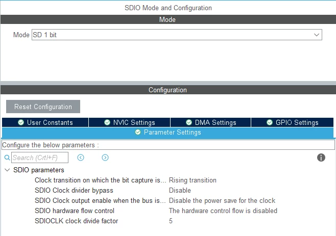
Okay, so first my config for WORKING 1 bit mode:
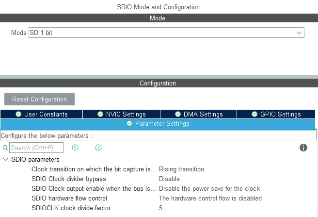
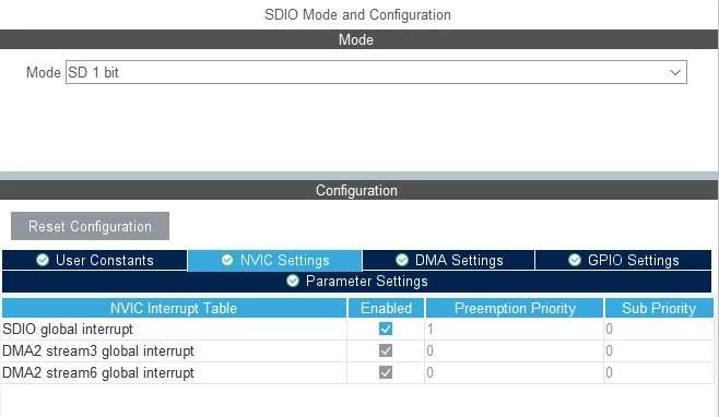
- SDIO global interrupt - disabled
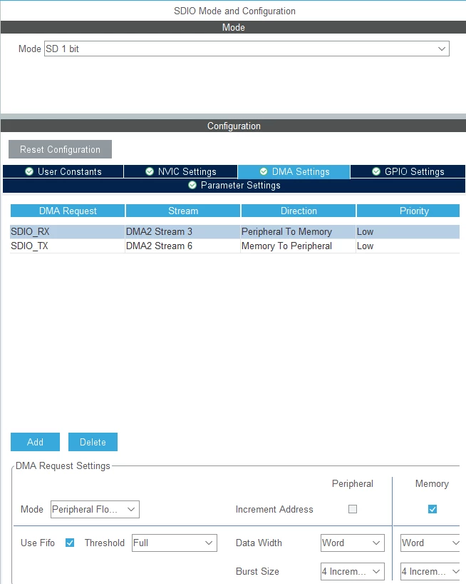
- no DMA
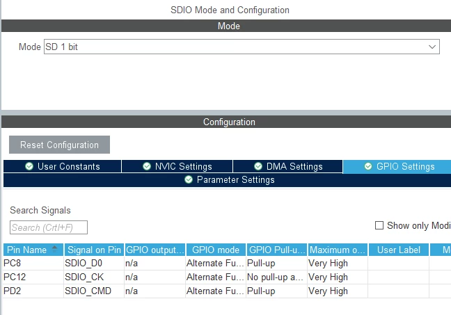
- no pull up's
- DMA template - disabled
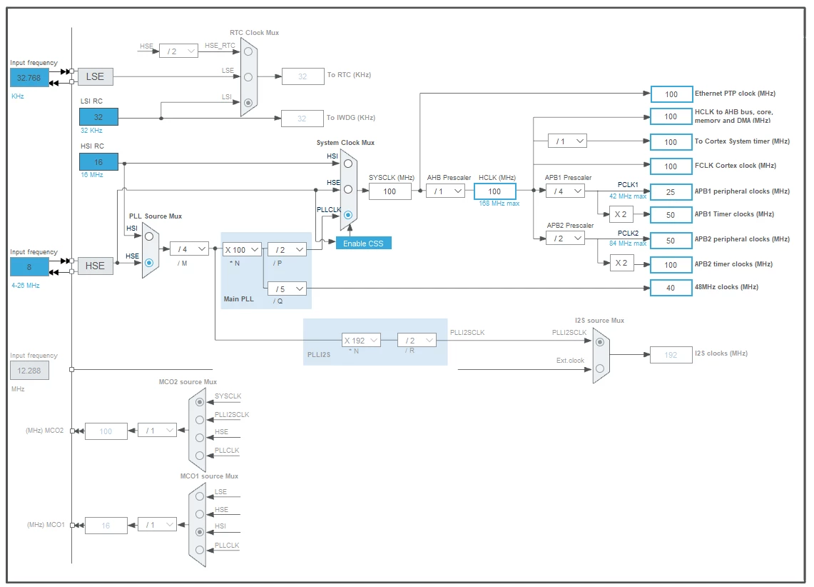
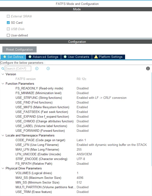
- Minimumm Heap Size 0x200
- Minimum Stack Size 0x400
Now, 1 bit + DMA mode, that's not working well. It reads fine, creates files, but ALWAYS double writes things to files!
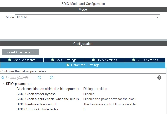
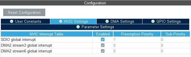
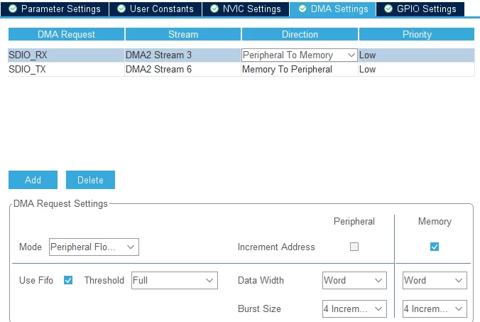
- Pull ups enabled or disabled, it doesn't make any diffrence
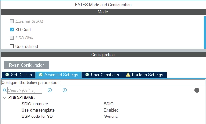
- DMA template - enabled
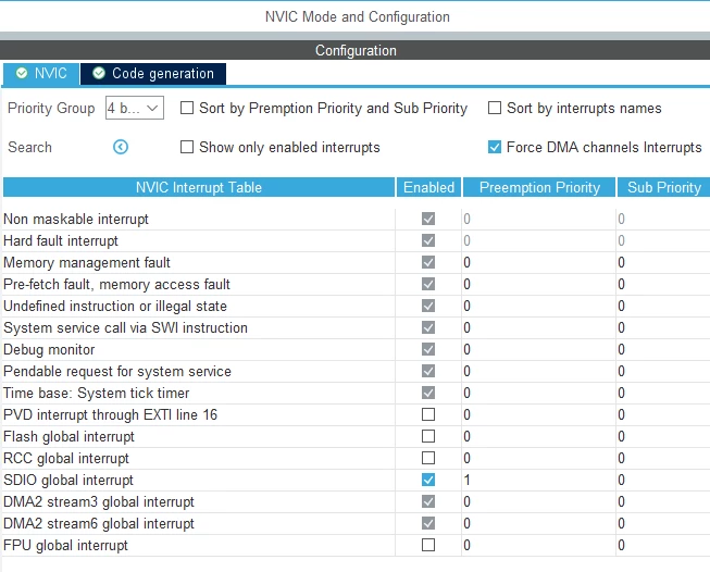
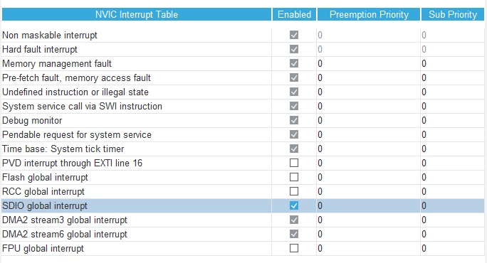 Now a little comment on the priority: I tried setting SDIO global interrupt preemption priority to 1 so it would be lower than dma's interrupt, but it didn't work.
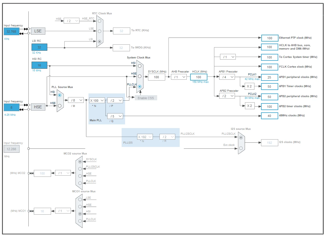
Clock configuration the same as in the previous example.
Also, I tried decreasing clock speed on SDIO, by setting APB2 to 24MHz, or by increasing the CLK divide factor - it didn't help.
Code:
static void MX_SDIO_SD_Init(void)
{

 /* USER CODE BEGIN SDIO_Init 0 */

 /* USER CODE END SDIO_Init 0 */

 /* USER CODE BEGIN SDIO_Init 1 */

 /* USER CODE END SDIO_Init 1 */
 hsd.Instance = SDIO;
 hsd.Init.ClockEdge = SDIO_CLOCK_EDGE_RISING;
 hsd.Init.ClockBypass = SDIO_CLOCK_BYPASS_DISABLE;
 hsd.Init.ClockPowerSave = SDIO_CLOCK_POWER_SAVE_DISABLE;
 hsd.Init.BusWide = SDIO_BUS_WIDE_1B;
 hsd.Init.HardwareFlowControl = SDIO_HARDWARE_FLOW_CONTROL_DISABLE;
 hsd.Init.ClockDiv = 5;
 /* USER CODE BEGIN SDIO_Init 2 */

 /* USER CODE END SDIO_Init 2 */

}
static void MX_DMA_Init(void)
{

 /* DMA controller clock enable */
 __HAL_RCC_DMA2_CLK_ENABLE();

 /* DMA interrupt init */
 /* DMA2_Stream3_IRQn interrupt configuration */
 HAL_NVIC_SetPriority(DMA2_Stream3_IRQn, 0, 0);
 HAL_NVIC_EnableIRQ(DMA2_Stream3_IRQn);
 /* DMA2_Stream6_IRQn interrupt configuration */
 HAL_NVIC_SetPriority(DMA2_Stream6_IRQn, 0, 0);
 HAL_NVIC_EnableIRQ(DMA2_Stream6_IRQn);

}

void HAL_SD_MspInit(SD_HandleTypeDef* hsd)
{
 GPIO_InitTypeDef GPIO_InitStruct = {0};
 if(hsd->Instance==SDIO)
 {
 /* USER CODE BEGIN SDIO_MspInit 0 */

 /* USER CODE END SDIO_MspInit 0 */
 /* Peripheral clock enable */
 __HAL_RCC_SDIO_CLK_ENABLE();

 __HAL_RCC_GPIOC_CLK_ENABLE();
 __HAL_RCC_GPIOD_CLK_ENABLE();
 /**SDIO GPIO Configuration
 PC8 ------> SDIO_D0
 PC12 ------> SDIO_CK
 PD2 ------> SDIO_CMD
 */
 GPIO_InitStruct.Pin = GPIO_PIN_8;
 GPIO_InitStruct.Mode = GPIO_MODE_AF_PP;
 GPIO_InitStruct.Pull = GPIO_PULLUP;
 GPIO_InitStruct.Speed = GPIO_SPEED_FREQ_VERY_HIGH;
 GPIO_InitStruct.Alternate = GPIO_AF12_SDIO;
 HAL_GPIO_Init(GPIOC, &GPIO_InitStruct);

 GPIO_InitStruct.Pin = GPIO_PIN_12;
 GPIO_InitStruct.Mode = GPIO_MODE_AF_PP;
 GPIO_InitStruct.Pull = GPIO_NOPULL;
 GPIO_InitStruct.Speed = GPIO_SPEED_FREQ_VERY_HIGH;
 GPIO_InitStruct.Alternate = GPIO_AF12_SDIO;
 HAL_GPIO_Init(GPIOC, &GPIO_InitStruct);

 GPIO_InitStruct.Pin = GPIO_PIN_2;
 GPIO_InitStruct.Mode = GPIO_MODE_AF_PP;
 GPIO_InitStruct.Pull = GPIO_PULLUP;
 GPIO_InitStruct.Speed = GPIO_SPEED_FREQ_VERY_HIGH;
 GPIO_InitStruct.Alternate = GPIO_AF12_SDIO;
 HAL_GPIO_Init(GPIOD, &GPIO_InitStruct);

 /* SDIO DMA Init */
 /* SDIO_RX Init */
 hdma_sdio_rx.Instance = DMA2_Stream3;
 hdma_sdio_rx.Init.Channel = DMA_CHANNEL_4;
 hdma_sdio_rx.Init.Direction = DMA_PERIPH_TO_MEMORY;
 hdma_sdio_rx.Init.PeriphInc = DMA_PINC_DISABLE;
 hdma_sdio_rx.Init.MemInc = DMA_MINC_ENABLE;
 hdma_sdio_rx.Init.PeriphDataAlignment = DMA_PDATAALIGN_WORD;
 hdma_sdio_rx.Init.MemDataAlignment = DMA_MDATAALIGN_WORD;
 hdma_sdio_rx.Init.Mode = DMA_PFCTRL;
 hdma_sdio_rx.Init.Priority = DMA_PRIORITY_LOW;
 hdma_sdio_rx.Init.FIFOMode = DMA_FIFOMODE_ENABLE;
 hdma_sdio_rx.Init.FIFOThreshold = DMA_FIFO_THRESHOLD_FULL;
 hdma_sdio_rx.Init.MemBurst = DMA_MBURST_INC4;
 hdma_sdio_rx.Init.PeriphBurst = DMA_PBURST_INC4;
 if (HAL_DMA_Init(&hdma_sdio_rx) != HAL_OK)
 {
 Error_Handler();
 }

 __HAL_LINKDMA(hsd,hdmarx,hdma_sdio_rx);

 /* SDIO_TX Init */
 hdma_sdio_tx.Instance = DMA2_Stream6;
 hdma_sdio_tx.Init.Channel = DMA_CHANNEL_4;
 hdma_sdio_tx.Init.Direction = DMA_MEMORY_TO_PERIPH;
 hdma_sdio_tx.Init.PeriphInc = DMA_PINC_DISABLE;
 hdma_sdio_tx.Init.MemInc = DMA_MINC_ENABLE;
 hdma_sdio_tx.Init.PeriphDataAlignment = DMA_PDATAALIGN_WORD;
 hdma_sdio_tx.Init.MemDataAlignment = DMA_MDATAALIGN_WORD;
 hdma_sdio_tx.Init.Mode = DMA_PFCTRL;
 hdma_sdio_tx.Init.Priority = DMA_PRIORITY_LOW;
 hdma_sdio_tx.Init.FIFOMode = DMA_FIFOMODE_ENABLE;
 hdma_sdio_tx.Init.FIFOThreshold = DMA_FIFO_THRESHOLD_FULL;
 hdma_sdio_tx.Init.MemBurst = DMA_MBURST_INC4;
 hdma_sdio_tx.Init.PeriphBurst = DMA_PBURST_INC4;
 if (HAL_DMA_Init(&hdma_sdio_tx) != HAL_OK)
 {
 Error_Handler();
 }

 __HAL_LINKDMA(hsd,hdmatx,hdma_sdio_tx);

 /* SDIO interrupt Init */
 HAL_NVIC_SetPriority(SDIO_IRQn, 0, 0);
 HAL_NVIC_EnableIRQ(SDIO_IRQn);
 /* USER CODE BEGIN SDIO_MspInit 1 */

 /* USER CODE END SDIO_MspInit 1 */
 }

}
Now, what I did:
- https://community.st.com/s/question/0D50X00009XkWceSAF/stm32f411re-stm32cube-fatfs-sdio-sdcard-always-returns-frdiskerr
- https://community.st.com/s/question/0D50X00009XkWt5SAF/solution-to-fix-stm32f4xxx-stmcubemx-firmware-v118-sdio-fatfs-dma-not-working-issue
- https://community.st.com/s/feed/0D50X00009XkVtKSAV
and a lot of forums posts and websites - nothing seems to help.
When I config to work in 4 bit mode mostly I get FR_DISK_ERR after closing a file, after creating a new one. Or the program just stops working and crashes.
My 4 bit config doesn't differ much from the 1 bit (expect there is 4 bit mode chosen), so i won't be posting it.
And what's important also - 4 bit gives me the same error in DMA mode too.
My another wonder is, why cubemx doesn't generate me lines in user code 2 section, in 4 bit mode:
static void MX_SDIO_SD_Init(void)
{

 /* USER CODE BEGIN SDIO_Init 0 */

 /* USER CODE END SDIO_Init 0 */

 /* USER CODE BEGIN SDIO_Init 1 */

 /* USER CODE END SDIO_Init 1 */
 hsd.Instance = SDIO;
 hsd.Init.ClockEdge = SDIO_CLOCK_EDGE_RISING;
 hsd.Init.ClockBypass = SDIO_CLOCK_BYPASS_ENABLE;
 hsd.Init.ClockPowerSave = SDIO_CLOCK_POWER_SAVE_DISABLE;
 hsd.Init.BusWide = SDIO_BUS_WIDE_1B;
 hsd.Init.HardwareFlowControl = SDIO_HARDWARE_FLOW_CONTROL_DISABLE;
 hsd.Init.ClockDiv = 7;
 /* USER CODE BEGIN SDIO_Init 2 */
 if (HAL_SD_Init(&hsd) != HAL_OK)
 {
 Error_Handler();
 }
 if (HAL_SD_ConfigWideBusOperation(&hsd, SDIO_BUS_WIDE_4B) != HAL_OK)
 {
 Error_Handler();
 }
 /* USER CODE END SDIO_Init 2 */

}
I found it on this post: https://community.st.com/s/question/0D53W00000sq1zbSAA/usb-msc-sdio-dma-combination-make-me-crazy-cant-solve-problem-help-needed-indeed
Are they necessery?
And one more question:
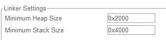
I tried increasing the minimum heap and stack size, but it doesn't make a difference to me, could anyone be kind to explain to me why it should be higher, and what size should work for FatFs?
I tried heap 0x2000 and stack 0x4000.
I will be enternally greatfull for your help on that problem.
Thanks!