Associate II
December 26, 2023
Solved

STM32 F4 CANBUS communication issue

Hello,

I am trying to program Can Bus protocol with two stm32 boards. I used MCP2551 and VP230 can transiciever but both of them doesnt work or my code doesnt work I dont know. I am programming normal mode. My purpose is when press the any button of boards the other board read the data of button interrupt and blink the led. This is for beginning. I am in progress of learning Can Bus protocol and this problem destroy me please help me :)

Here is my code 

/* USER CODE BEGIN 0 */

CAN_TxHeaderTypeDef pHeader;

CAN_RxHeaderTypeDef pRxHeader;

CAN_FilterTypeDef sFilterConfig;

uint32_t pTxMailbox;

uint8_t count=0;

uint8_t rcount=0;

/* USER CODE END 0 */


/* Initialize all configured peripherals */

MX_GPIO_Init();

MX_CAN1_Init();

/* USER CODE BEGIN 2 */

HAL_CAN_Start(&hcan1);

// Activate Interrupts

HAL_CAN_ActivateNotification(&hcan1,CAN_IT_RX_FIFO0_MSG_PENDING);

// set transmit parameteres

pHeader.DLC = 1;

pHeader.IDE = CAN_ID_STD;

pHeader.RTR = CAN_RTR_DATA;

pHeader.StdId = 0x0155;

// Set Filter Parameters

sFilterConfig.FilterActivation = ENABLE;

sFilterConfig.FilterBank = 0 ; // tekli kullanimda 0-13 arasi deger alir ikili kullanimda 0-27 arası

sFilterConfig.FilterFIFOAssignment=CAN_FILTER_FIFO0; // filtre hangi fifoya girecek

sFilterConfig.FilterIdHigh = 0x0000;

sFilterConfig.FilterIdLow = 0x0000 ;

sFilterConfig.FilterMaskIdHigh=0x000;

sFilterConfig.FilterMode = CAN_FILTERMODE_IDMASK; // hangi filtre modu

sFilterConfig.FilterScale = CAN_FILTERSCALE_32BIT;

HAL_CAN_ConfigFilter(&hcan1, &sFilterConfig);

/* USER CODE END 2 */


This section is interrupt file in SRC

oid EXTI0_IRQHandler(void)

{

/* USER CODE BEGIN EXTI0_IRQn 0 */


/* USER CODE END EXTI0_IRQn 0 */

HAL_GPIO_EXTI_IRQHandler(GPIO_PIN_0);

/* USER CODE BEGIN EXTI0_IRQn 1 */

if(GPIO_PIN_0==GPIO_PIN_0)

{

count++;

HAL_CAN_AddTxMessage(&hcan1,&pHeader,&count,&pTxMailbox);


}

/* USER CODE END EXTI0_IRQn 1 */

}


/**

* @brief This function handles CAN1 RX0 interrupts.

*/

void CAN1_RX0_IRQHandler(void)

{

/* USER CODE BEGIN CAN1_RX0_IRQn 0 */


/* USER CODE END CAN1_RX0_IRQn 0 */

HAL_CAN_IRQHandler(&hcan1);

/* USER CODE BEGIN CAN1_RX0_IRQn 1 */

HAL_CAN_GetRxMessage(&hcan1,CAN_RX_FIFO0,&pRxHeader,&rcount);

GPIOD->ODR = rcount << 12;

/* USER CODE END CAN1_RX0_IRQn 1 */

}

This topic has been closed for replies.
mƎALLEm
mƎALLEmBest answer
ST Technical Moderator
December 28, 2023

Hello,

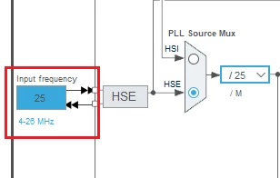
Could you please confirm that your clock source you're using is a 25MHz crystal?

As per your CubeMx configuration? Could you please tell what is the board you are using is it a STM32F4-DISCO board?

SofLit_1-1703787308380.png

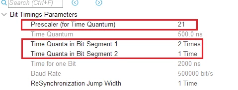
Also, I'm not in favor of these parameters as BS1 and BS2 are too small value with a big prescaler. Please increase BS1 and BS2 and decrease the prescaler with BS1 = ~(70% to 80%) of (BS1+BS2)

SofLit_0-1703787271848.png

From HW point of view. Is that you who designed that circuit or is it a transceiver module you've purchased?

- The termination resistors are 120ohm and not 60ohm

- Could you also connect Rs pins directly to the GND?

- What is the purpose of 30pF capacitors connected to Rx pins?


To give better visibility on the answered topics, please click "Best answer" on the reply which solved your issue or answered your question.

8 replies

Johi
Senior II
December 26, 2023

You can start by polling as in the example attached.

It uses the 2 Can buses on my STM32F407.


maZersAuthor
Associate II
December 26, 2023

Thank you so much. This will be useful for the beginning. But I have to communicate with two boards. I just want to see my mistake. This is so meaningless. In my code, the transmision is okey but receiving doesnt work. The baudrates are same on two board. It is 500000 bit/s. The program doesnt even get in CanRxFIFO0 callback function. I am sure the connections with MCP2551 and boards. In addition maybe it helps, Can H and Can L line are voltage is 2,7V but I guess Can H line voltage should be higher than 2,5V the Can L line should be lower than 2,5V. Is this all problem ? Is My can transceiver IC broke ? 

mƎALLEm
ST Technical Moderator
December 27, 2023

@maZers ,

Please provide your schematics.

Please provide your CAN configuration (if possible attach your project)

To give better visibility on the answered topics, please click "Best answer" on the reply which solved your issue or answered your question.
maZersAuthor
Associate II
December 28, 2023

Here is my main.c ,  it.c files and CAN configuration. Thank you for helping.

maZersAuthor
Associate II
December 28, 2023

Also, here is my schematic 

mƎALLEm
mƎALLEmBest answer
ST Technical Moderator
December 28, 2023

Hello,

Could you please confirm that your clock source you're using is a 25MHz crystal?

As per your CubeMx configuration? Could you please tell what is the board you are using is it a STM32F4-DISCO board?

SofLit_1-1703787308380.png

Also, I'm not in favor of these parameters as BS1 and BS2 are too small value with a big prescaler. Please increase BS1 and BS2 and decrease the prescaler with BS1 = ~(70% to 80%) of (BS1+BS2)

SofLit_0-1703787271848.png

From HW point of view. Is that you who designed that circuit or is it a transceiver module you've purchased?

- The termination resistors are 120ohm and not 60ohm

- Could you also connect Rs pins directly to the GND?

- What is the purpose of 30pF capacitors connected to Rx pins?


To give better visibility on the answered topics, please click "Best answer" on the reply which solved your issue or answered your question.
maZersAuthor
Associate II
January 3, 2024

hello, 

I am using MCP2551 can transceiver IC and I made a circuit according to its datasheet. I just made recommended connection in datasheet.

the connection that I get from datasheet is attached

Also, I increased the bs1/bs1+bs2 to %75 and decreased the prescaler so my system worked.the receiving is succesfull.

Thank you so much :) 

Screenshot_2024-01-03-07-47-21-152_com.google.android.apps.docs.jpg

o much :) 

maZersAuthor
Associate II
December 28, 2023

okey ı will try increase BS1 and BS2 and also decrease the prescaler thank you. By the way, I actually have should altered the input frequency to 8Mhz

My board is also stm32f4 disco

Thank you so much I will follow your ideas and back here soon.