SGasp.1
Associate III
January 11, 2024
Solved

SPI pin for STM32F429

  • January 11, 2024
  • 7 replies
  • 3531 views

Hi community, just a single question as confirm. 


I am working with stm32f429.

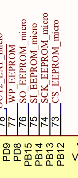
From the schematic the hw engineer decided to use the following pin for spi purpose for communicating with an eeprom 
 

SGasp1_0-1704962915971.png

Can you confirm that i cannot use those pins for spi purpose ? 

(i have tried to select sp1,sp2,sp3,sp4,sp5,sp6)


Thanks a lot 

This topic has been closed for replies.
Best answer by AScha.3

>the point is is all the pins are ok for spi and how to change the proposed pins in cube mx 

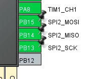
check = exactly this. Is possible ? -> ok , then click on each pin and select the function you want , spi2xxx here.

ready . Now they are "user defined" (pinned) on this position.

AScha3_0-1704966486036.png

And set in configuration SPI2 -> full duplex master (or what you need for your eeprom access ).

7 replies

AScha.3
Super User
January 11, 2024

F429  - case ?

from ds , p.62:     PB13 , should be sck_eeprom - right ?  


AScha3_0-1704965042169.png

-> spi2_sck is possible, so check , for other pins for your eeprom on SPI2 ;

pin74 --> LQFP144 .

+

When in Cube select/activate spi2 , then can choose also alternative pins for some peripherals ;

you can select them manually, click on the pin and choose..

AScha3_1-1704965464822.png


If you feel a post has answered your question, please click on " Best Answer ".
SGasp.1
SGasp.1Author
Associate III
January 11, 2024

Hi @AScha.3 ,


thanks for the quick reply

case is stm32f429zit6,


what do you mean for spi2_sck is possible, so check , for other pins for your eeprom on SPI2 ;?


the point is is all the pins are ok for spi and how to change the proposed pins in cube mx 


Thanks

AScha.3
AScha.3Best answer
Super User
January 11, 2024

>the point is is all the pins are ok for spi and how to change the proposed pins in cube mx 

check = exactly this. Is possible ? -> ok , then click on each pin and select the function you want , spi2xxx here.

ready . Now they are "user defined" (pinned) on this position.

AScha3_0-1704966486036.png

And set in configuration SPI2 -> full duplex master (or what you need for your eeprom access ).

If you feel a post has answered your question, please click on " Best Answer ".
SGasp.1
SGasp.1Author
Associate III
January 11, 2024

IT IS ok the only thing that it ssems that mosi and miso are inverted 


Thanks @AScha.3 

AScha.3
Super User
January 11, 2024

>mosi and miso are inverted 

signal inverted ? pins exchanged ?


If you feel a post has answered your question, please click on " Best Answer ".
Andrew Neil
Super User
January 11, 2024

@AScha.3 - "pins exchanged ?"

Look at the diagrams:

AndrewNeil_0-1704969279505.png AndrewNeil_1-1704969292637.png

  • PB15 is MOSI: you have that connected to "SO_EEPROM_micro" - is that correct for your system?
  • PB14 is MISO:  you have that connected to "SI_EEPROM_micro" - is that correct for your system?


This is why names like "SI" and "SO" are best avoided: they are ambiguous - does your "SO" mean output from the MCU to the EEPROM, or output from the EEPROM to the MCU?

Using MISO and MOSI*  removes this ambiguity!


* or modern alternatives alternatives like PICO and POCI: https://www.sparkfun.com/spi_signal_names 

A complex system that works is invariably found to have evolved from a simple system that worked.A complex system designed from scratch never works and cannot be patched up to make it work.