Associate
August 6, 2026
Question

Some of STM32 IO pin change logic from default logic during reset release

  • August 6, 2026
  • 14 replies
  • 115 views

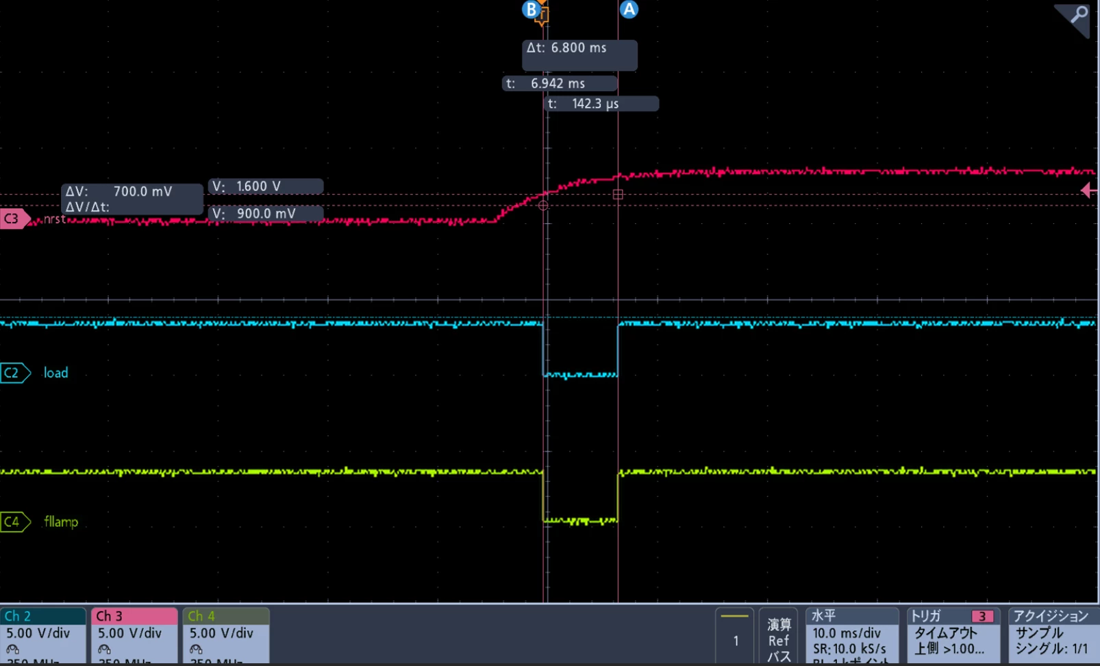
I am doing a project on STM32F479ZGT6. I set all my pins to HIGH default, open drain, external pull up on STMCubeMX. During power on, the IO pins first follows 3.3V by the external pull up, but then two of the IO pins becomes LOW during reset release, and then after reset is completely released, it turns back to HIGH(default logic set in STMCubeMX). Does STM32 has the ability to change logic opposite from the default logic only for a moment?(which in my case is during reset release) Would be glad to know any possible cause and solution for this case.

Red: Reset

Blue &Green: IO pin
 

14 replies

TDK
August 6, 2026

The vast majority of pins are in a high-z state when the chip is in reset. There is no ability to change this behavior.

If you need a pin to be in a defined state, the only way is to use an external pullup or pulldown resistor.

I set all my pins to HIGH default, open drain, external pull up

“External” pull up is not a setting in STM32CubeMX. The pullup/pulldown settings refer to internal pullup/pulldown resistors.

"If you feel a post has answered your question, please click ""Accept as Solution""."
adibahqinAuthor
Associate
August 6, 2026

I beg your pardon. For the STMCubeMX setting, I set it to no internal pull up/pull down and then connect it to external pull up. The connected external pull up should be not making the IO pin to be left floating.

TDK
August 6, 2026

I beg your pardon. For the STMCubeMX setting, I set it to no internal pull up/pull down and then connect it to external pull up. The connected external pull up should be not making the IO pin to be left floating.

Ahh, so the problem is the pin is getting pulled low at/during startup. Which pins are these? Are you setting the state to high before you make them an output? Does it happen if you leave the pin as input?

"If you feel a post has answered your question, please click ""Accept as Solution""."
Richard Li
Senior
August 6, 2026

You can try make reset signal more sharp, reduce capacitor at NRST, even use reset IC like TI TPS3703, TPS3899…

If this doesn’t work, you can play with PDR_ON pin, change different power on reset.

More than this, you need carefully control power on/off sequency, 

If power sequency no good, your product lifetime may reduce.

Explorer
August 6, 2026

Really odd.
You can state WHICH TWO PINS of STM32F479ZGT6, and then let’s check the DS&RM.
Some specific alternate functions related, maybe.

Richard Li
Senior
August 6, 2026

In reset signal not stable period, (in your case 0.9V - 1.6V) chip status is unknown, This is normal for most chip. 

TDK
August 6, 2026

The chip status is either in reset, or it has started. In either case, the pin should be high provided the initialization is correct. I don’t see how this explains anything.

It is not normal for pins to toggle during startup.

"If you feel a post has answered your question, please click ""Accept as Solution""."
adibahqinAuthor
Associate
August 7, 2026

Yeah there is a possibility that during the interval the logic changes, it enters mode other than main program.

Btw, I think I have found the possible cause, and Ive posted in the reply. 

Not sure if it makes sense, but let me know if you guys have any thoughts about it.

Andrew Neil
Super User
August 6, 2026

Welcome to the forum

Please see How to write your question to maximize your chances to find a solution for best results.


In particular, as the others have said, you need to state which pins you’re looking at.

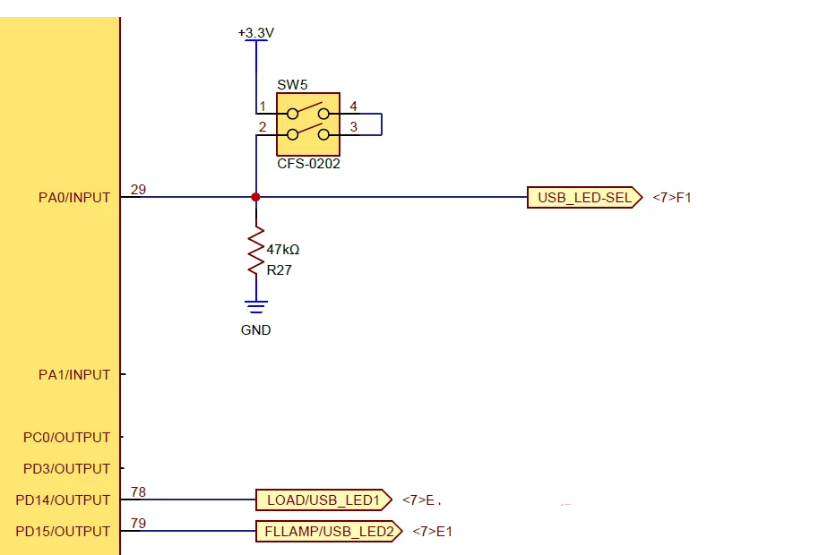
Also, show the schematic.

Some good, clear photos of your setup may also help.

A complex system that works is invariably found to have evolved from a simple system that worked.A complex system designed from scratch never works and cannot be patched up to make it work.
adibahqinAuthor
Associate
August 7, 2026

Thank you for the advice. I think I have found the cause.

In my circuit, the 2 GPIO pins are sharing with the same pins used for program updater. The function of the IO pins (normal operation mode) and the program updater LED pins (program updater mode) are selected by receiving input from DIPSW.

For example, 

DIPSW ON: USB programmer mode, function as USB LED pin

DIPSW OFF: Normal operation mode, function as IO output(FLLAMP, LOAD) 

After STM32 reset release, it will run program updater first as far as I know.

  1. Power on
  2. CPU reset
  3. CPU release
  4. Run bootloader
  5. Enter program updater mode, to check USB presence. If not, run main program.

The sudden LOW is the logic programmed in program updater. But because I set the DIPSW to normal operation mode, and no USB detected, it breaks from the program updater code and run the main program. Because the default logic of the IO pin in main program is HIGH, it turns LOW→HIGH as shown in the waveform. So, apparently because the general IO pins and program updater pins are used on the same pin, the default logic of IO pin will change if the default logic for program updater and main program is different.

So, in order to solve this, set both program updater logic and main program logic to the same logic to prevent irrelevant logic change during startup.


Richard Li
Senior
August 7, 2026

All program should start after reset release, meaning after reset rising to Vhigh * 0,7 , so your scope show these pins low didn’t cause by ant program. 

Richard Li
Senior
August 7, 2026

In big chip manufactory, our chip validation include test boot time reset, Voltage rising-falling time issue, this may not critical, depends use case, only one glitch, you should use scope look reset-vdd relate time, if reset release before VDD stable, you got more troble.

Early I noticed power sequency, in datasheet, it noticed, VDDUSB should after VDD.

In our group, test boot time cost one engineer more than one week.