Associate III
November 14, 2024
Solved

Shifts in conversion data from ADC on STM32H7B3

Hi!

We are characterizing the ADC's in the STM32H7B3 µc. During temperature cycling of the HW we are observing some unexpected shifts in the conversion data from the ADC. The phenomena is observed across multiple HW units in varying degree. 

From one part: 
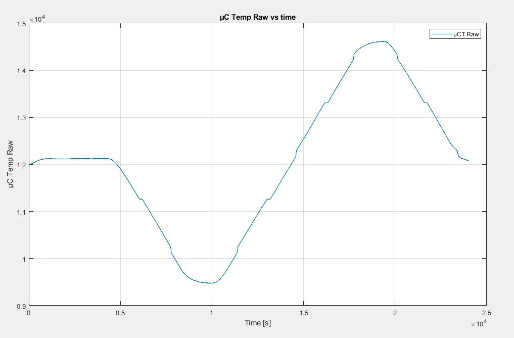
HansPLJ_1-1731599396212.png

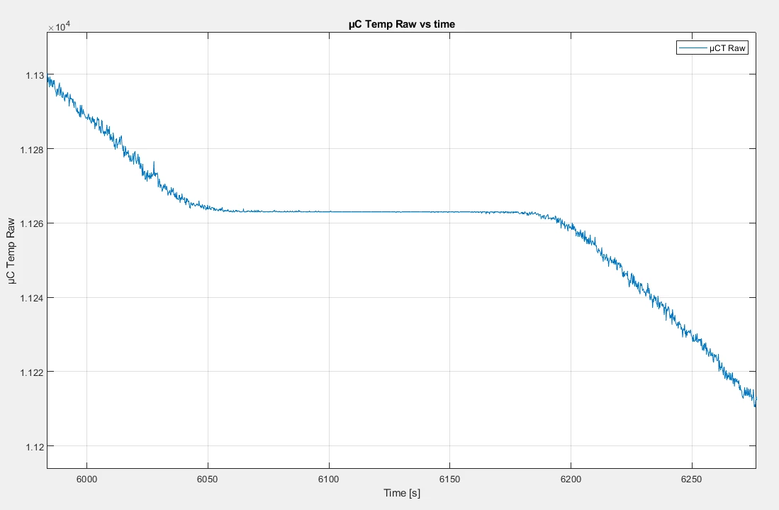
 Zoomed in at the first shift:

HansPLJ_3-1731599807259.png

It seems 'stuck' at 11263 (decimal) = 0b 0010 1011 1111 1111

From another part: 
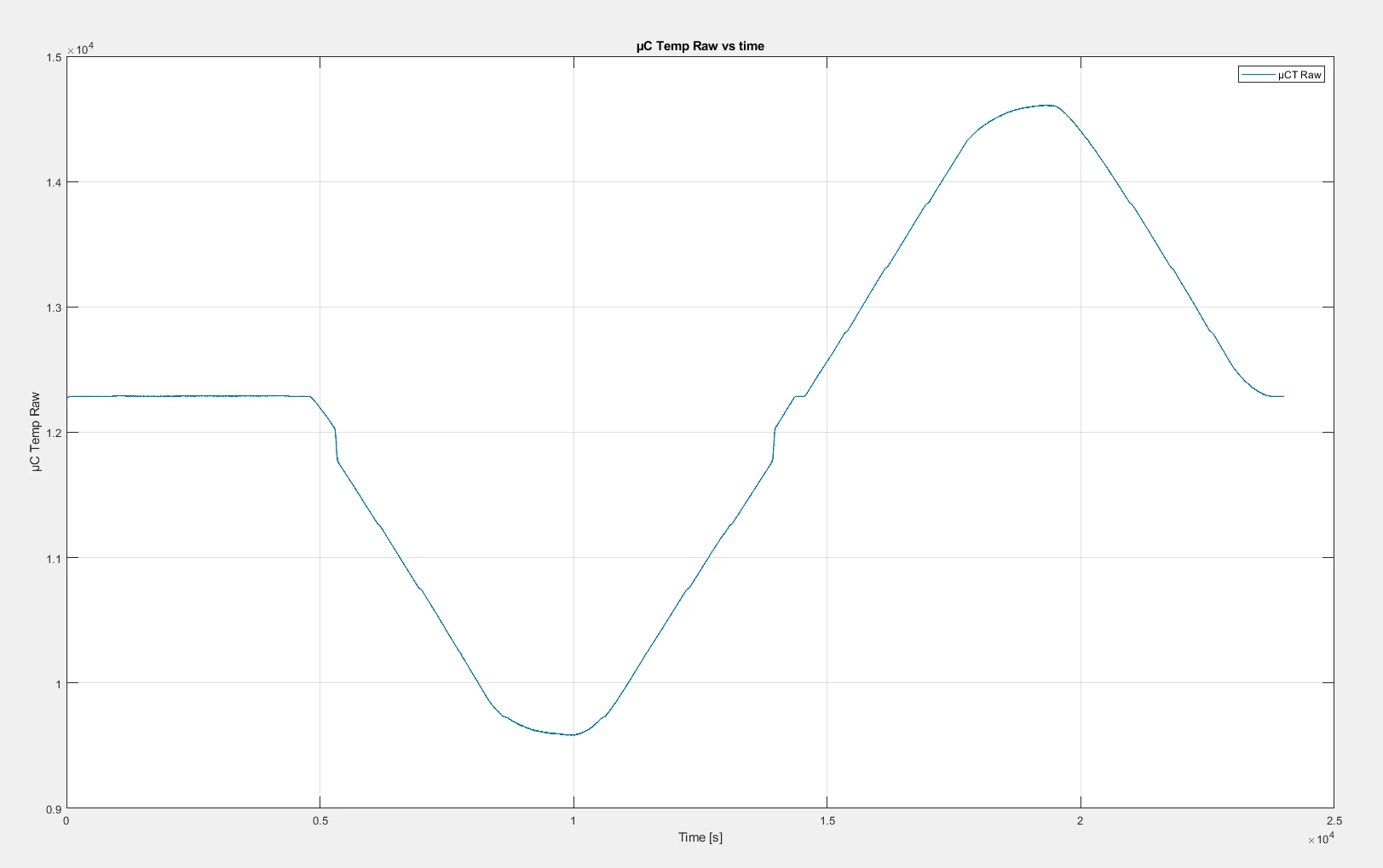
HansPLJ_2-1731599466111.png


It looks like the shifts are occurring at the some distinct digital values. Is seems like there is a tendency that when the 8 LSB of the digital value are all zeros or all ones, a shift occurs. I can provide raw data if this is of use.  

Has anyone at ST seen this sort of behavior from the ADC's? If there is a weakness in the design of the ADC's we need to identify it early. 

Hopefully this is due to some configuration error on our part. 

The ADC is configured like this; 

m_adcHandle.Init.ClockPrescaler = ADC_CLOCK_ASYNC_DIV1;
m_adcHandle.Init.Resolution = ADC_RESOLUTION_16B;
m_adcHandle.Init.ScanConvMode = ADC_SCAN_ENABLE;
m_adcHandle.Init.EOCSelection = ADC_EOC_SEQ_CONV;
m_adcHandle.Init.LowPowerAutoWait = DISABLE;
m_adcHandle.Init.ContinuousConvMode = ENABLE;
m_adcHandle.Init.DiscontinuousConvMode = DISABLE;
m_adcHandle.Init.ExternalTrigConv = ADC_EXTERNALTRIG_T8_TRGO;
m_adcHandle.Init.ExternalTrigConvEdge = ADC_EXTERNALTRIGCONVEDGE_RISING;
m_adcHandle.Init.ConversionDataManagement = ADC_CONVERSIONDATA_DMA_CIRCULAR;
m_adcHandle.Init.Overrun = ADC_OVR_DATA_PRESERVED;
m_adcHandle.Init.LeftBitShift = ADC_LEFTBITSHIFT_NONE;
m_adcHandle.Init.OversamplingMode = ENABLE;
m_adcHandle.Init.Oversampling.Ratio = ADC1_OVERSAMPLING_RATIO;
m_adcHandle.Init.Oversampling.RightBitShift = ADC_RIGHTBITSHIFT_4;
m_adcHandle.Init.Oversampling.OversamplingStopReset = ADC_REGOVERSAMPLING_CONTINUED_MODE;

The oversampling ratio is 16 and the sample time is 810.5 cycles. The ADC is clocked at 4 MHz. I am running the offset calibration routine during start-up. The conversion is triggered by timer8 at 50 Hz. 

If more information is needed to provide support, let my know and I will supply. 

Best regards,

Hans-Petter Lund Jørgensen 
This topic has been closed for replies.
HansPLJBest answer
Associate III
November 18, 2024

Hi again!

Since the converted µ-controller temperature also has the lost code -shifts, I do not see how the 47kOhm impedance can be the root cause? 

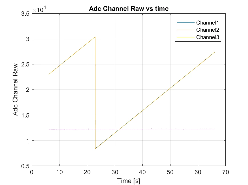
I have tried to apply the linearity calibration routine during start-up. It appears that the shifts is no longer apparent:

HansPLJ_0-1731940037273.png


 I will do more measurements tonight to see if the issue is gone. 


Best regards, 

Hans-Petter 


9 replies

waclawek.jan
Super User
November 14, 2024

Missing codes may be consequence of inadequate reference, but if it can be directly linked to changing temperature, then you may simply need to recalibrate upon those temperature changes. 

Btw. I wouldn't be using oversampling for this kind of tests as it may hide some imperfections, and I would use linearly ramping (triangular) input signal.

JW

HansPLJAuthor
Associate III
November 15, 2024

Thanks for the feedback. We will look into the inadequate reference when we have a setup that reproduces the phenomena. 

Best regards, 

Hans-Petter 

STOne-32
ST Technical Moderator
November 14, 2024

Dear @HansPLJ ,

Can you please give is more details on testing procedure so we can try to reproduce it ? And in particular :

”During temperature cycling of the HW” if possible to have the exact profile of temperature applied . What are the Y axis  of the graphs  ( is it the Converted value ) .


Regarding the calibration , it is highly recommend to run it each time VDDA or temperature change , I would suspect a link with this point .

Hope it helps ,

STOne-32


HansPLJAuthor
Associate III
November 15, 2024

Thanks for your reply! 

This is data logged from a reference temperature sensor:

HansPLJ_0-1731661871052.png

We are stabilizing at 25°C, lowering temperature to -40°C, rising temperature to 80°C and ending at 25°C. 

The Y-axis is the converted raw value from the ADC. 


I am troubleshooting this today and will supply more information when I have it. 

Best regards, 

Hans-Petter 

STOne-32
ST Technical Moderator
November 15, 2024

Dear @HansPLJ ,

 I saw you are using a High Impedance Input of 47Kohm on the PC3-5 But if you look to our datasheet : you can see that we define Maximum RAIN to 170Ohm in 16-bits resolution

Datasheet - STM32H7B0xB - 32-bit Arm® Cortex®-M7 280 MHz MCUs, 128-Kbyte Flash memory, 1.4-Mbyte RAM, 46 com. and analog interfaces, SMPS, crypto

STOne32_0-1731705943236.png


and I see you are using a big Cext of 100nF which is recommended in our Application Note : How to optimize the ADC accuracy in the STM32 MCUs - Application note  but not sure at this 16bits resolution.    I would suggest to apply Calibration and try for testing purposes to use a low impedance source if the behavior still the same ( only for testing).

Hope it helps you.

Ciao

STOne-32.

waclawek.jan
Super User
November 16, 2024

This is exactly what "lost code" means.

Besides the input circuit perhaps not being entirely optimal as @STOne-32  said above, the reference circuit may also be not perfect - some 100nF have too high impedance at the ADC/conversion frequency i.e. 80MHz; and also layout matters, too, e.g. inductances of too long tracks. Besides, grounding arrangement (and again, layout) matters as well.

Also, have you performed the ADC calibration after the temperature has been changed (e.g. as consequence of having the mcu running), as suggested above?

> frequency of 80 mHz

80 milliHertzs? :) (That (LT)Spice customarily supports this, does not make it right).

JW


HansPLJAuthorBest answer
Associate III
November 18, 2024

Hi again!

Since the converted µ-controller temperature also has the lost code -shifts, I do not see how the 47kOhm impedance can be the root cause? 

I have tried to apply the linearity calibration routine during start-up. It appears that the shifts is no longer apparent:

HansPLJ_0-1731940037273.png


 I will do more measurements tonight to see if the issue is gone. 


Best regards, 

Hans-Petter 


STOne-32
ST Technical Moderator
November 18, 2024

Dear @HansPLJ 

"have tried to apply the linearity calibration routine during start-up. It appears that the shifts is no longer apparent:"

>> Excellent finding !