

Solved
Setting up RTCC with LSE 32.768kHz Crystal
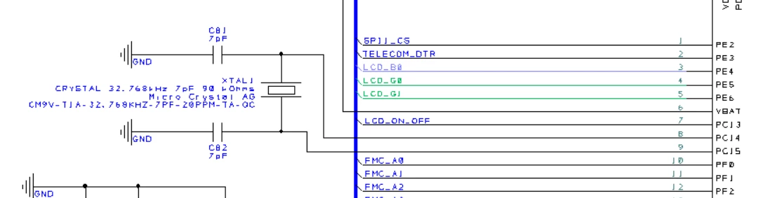
Hardware 1: STM32F767ZGT6 with LSE Crystal Model: CM9V-T1A-32.768KHZ-7PF-20PPM-TA-QC Maker: Micro Crystal AG
Hardware 2: STM32F767IIT6 with LSE Crystal Model: ECS-.327-12.5-12R-C-TR Maker: ECS Inc
Compiler: IAR Workbench v8.32.1
Driver: STM32Cube_FW_F7_V1.15.0
Hi.
I have two PCB designs with the above different MCU and LSE crystals chosen from AN4759. However, HAL_RTC_Init(…) usually fails and when it does work the RTC clock is very inaccurate. Can someone please advise what I am doing wrong in by code?
Regards, Andrew
#include "stm32f7xx_ll_bus.h"
#include "stm32f7xx_ll_rcc.h"
#include "stm32f7xx_ll_system.h"
#include "stm32f7xx_ll_utils.h"
#include "stm32f7xx_ll_gpio.h"
#include "stm32f7xx_ll_rtc.h"
#include "stm32f7xx_ll_pwr.h"
#include "stm32f7xx_ll_cortex.h"
#include "main.h"

extern RTC_HandleTypeDef hRTC_Handle;

int main(void)
{
 RCC_ClkInitTypeDef RCC_ClkInitStruct;
 RCC_OscInitTypeDef RCC_OscInitStruct;
 RCC_PeriphCLKInitTypeDef PeriphClkInitStruct;
 HAL_StatusTypeDef ret = HAL_OK;
 uint8_t aShowTime[50] = {0};
 uint8_t aShowDate[50] = {0};


 /* Enable the CPU Cache */
 CPU_CACHE_Enable();

 /* STM32F7xx HAL library initialization */
 HAL_Init();

 /* Resets the RCC clock configuration to the default reset state. */
 HAL_RCC_DeInit();

 /* Enable HSE Oscillator and activate PLL with HSE as source */
 RCC_OscInitStruct.OscillatorType = RCC_OSCILLATORTYPE_HSE;
 RCC_OscInitStruct.HSEState = RCC_HSE_BYPASS;
 RCC_OscInitStruct.LSEState = RCC_LSE_ON;
 RCC_OscInitStruct.HSIState = RCC_HSI_OFF;
 RCC_OscInitStruct.HSICalibrationValue = RCC_HSICALIBRATION_DEFAULT;
 RCC_OscInitStruct.LSIState = RCC_LSI_OFF;
 RCC_OscInitStruct.PLL.PLLState = RCC_PLL_ON;
 RCC_OscInitStruct.PLL.PLLSource = RCC_PLLSOURCE_HSE;
 RCC_OscInitStruct.PLL.PLLM = 24;
 RCC_OscInitStruct.PLL.PLLN = 400;
 RCC_OscInitStruct.PLL.PLLP = RCC_PLLP_DIV2;
 RCC_OscInitStruct.PLL.PLLQ = 8;
 RCC_OscInitStruct.PLL.PLLR = 2;

 ret = HAL_RCC_OscConfig(&RCC_OscInitStruct);
 if(ret != HAL_OK)
 {
 while(1) { ; }
 }

 /* Activate the OverDrive to reach the 200 MHz Frequency */
 ret = HAL_PWREx_EnableOverDrive();
 if(ret != HAL_OK)
 {
 while(1) { ; }
 }

 /* Select PLL as system clock source and configure the HCLK, PCLK1 and PCLK2 clocks dividers */
 RCC_ClkInitStruct.ClockType = (RCC_CLOCKTYPE_SYSCLK | RCC_CLOCKTYPE_HCLK | RCC_CLOCKTYPE_PCLK1 | RCC_CLOCKTYPE_PCLK2);
 RCC_ClkInitStruct.SYSCLKSource = RCC_SYSCLKSOURCE_PLLCLK;
 RCC_ClkInitStruct.AHBCLKDivider = RCC_SYSCLK_DIV1;
 RCC_ClkInitStruct.APB1CLKDivider = RCC_HCLK_DIV4;
 RCC_ClkInitStruct.APB2CLKDivider = RCC_HCLK_DIV2;

 ret = HAL_RCC_ClockConfig(&RCC_ClkInitStruct, FLASH_LATENCY_6);
 if(ret != HAL_OK)
 {
 while(1) { ; }
 }

 /* Select PLLSAI output as USB clock source */
 PeriphClkInitStruct.PeriphClockSelection = (RCC_PERIPHCLK_RTC | RCC_PERIPHCLK_UART7 | RCC_PERIPHCLK_CLK48 | RCC_PERIPHCLK_UART5 | RCC_PERIPHCLK_LTDC);
 PeriphClkInitStruct.RTCClockSelection = RCC_RTCCLKSOURCE_LSE;
 PeriphClkInitStruct.Clk48ClockSelection = RCC_CLK48SOURCE_PLLSAIP;
 PeriphClkInitStruct.Uart7ClockSelection = RCC_UART7CLKSOURCE_PCLK1;
 PeriphClkInitStruct.Uart5ClockSelection = RCC_UART5CLKSOURCE_PCLK1;

 PeriphClkInitStruct.PLLSAI.PLLSAIN = 192;
 PeriphClkInitStruct.PLLSAI.PLLSAIP = RCC_PLLSAIP_DIV4;
 PeriphClkInitStruct.PLLSAI.PLLSAIQ = 2;
 PeriphClkInitStruct.PLLSAIDivQ = 1;
 PeriphClkInitStruct.PLLSAI.PLLSAIR = 5;
 PeriphClkInitStruct.PLLSAIDivR = RCC_PLLSAIDIVR_4;

 if (HAL_RCCEx_PeriphCLKConfig(&PeriphClkInitStruct) != HAL_OK)
 {
 while(1) { ; }
 }

 /* Setup UART DeBug Terminal */
 Print_DeBug_Initialise();

 /* Enable RTC Clock */
 __HAL_RCC_RTC_ENABLE();

 /* Setup RTCC */
 hRTC_Handle.Instance = RTC;
 hRTC_Handle.Init.HourFormat = RTC_HOURFORMAT_12;
 hRTC_Handle.Init.AsynchPrediv = 127; // 127 + 1 = 128
 hRTC_Handle.Init.SynchPrediv = 255; // 255 + 1 = 256 32768Hz / 128 / 256 = 1Hz
 hRTC_Handle.Init.OutPut = RTC_OUTPUT_DISABLE;
 hRTC_Handle.Init.OutPutPolarity = RTC_OUTPUT_POLARITY_HIGH;
 hRTC_Handle.Init.OutPutType = RTC_OUTPUT_TYPE_PUSHPULL;
 /*********************** Need to add this to allow PC13 to work as normal GPIO ***********************************/
 hRTC_Handle.Instance->CR &= ((uint32_t) ~(RTC_CR_COE | RTC_CR_OSEL | RTC_CR_TSE));
 hRTC_Handle.Instance->TAMPCR &= ((uint32_t) ~(RTC_TAMPCR_TAMP1E) );
 /*********************** Need to add this to allow PC13 to work as normal GPIO ***********************************/

 ret = HAL_RTC_Init(&hRTC_Handle);
 if(ret != HAL_OK)
 {
 printf("ERROR - HAL_RTC_Init(&hRTC_Handle)\n\r");
 }


 while (1)
 {
 sprintf((char*)aShowTime,"%.2d:%.2d:%.2d", __LL_RTC_CONVERT_BCD2BIN(LL_RTC_TIME_GetHour(RTC)),
 __LL_RTC_CONVERT_BCD2BIN(LL_RTC_TIME_GetMinute(RTC)),
 __LL_RTC_CONVERT_BCD2BIN(LL_RTC_TIME_GetSecond(RTC)));
 /* Display date Format : mm-dd-yy */
 sprintf((char*)aShowDate,"%.2d-%.2d-%.2d", __LL_RTC_CONVERT_BCD2BIN(LL_RTC_DATE_GetMonth(RTC)),
 __LL_RTC_CONVERT_BCD2BIN(LL_RTC_DATE_GetDay(RTC)),
 2000 + __LL_RTC_CONVERT_BCD2BIN(LL_RTC_DATE_GetYear(RTC)));

 printf( "%s\n\r", aShowTime );
 printf( "%s\n\r", aShowDate );

 HAL_Delay(1000);
 }
}