


SIDRI.1
Associate III
May 31, 2021 7:46 AM UTC
Solved

Sending AT command to esp8266 using stm32F103 through usart
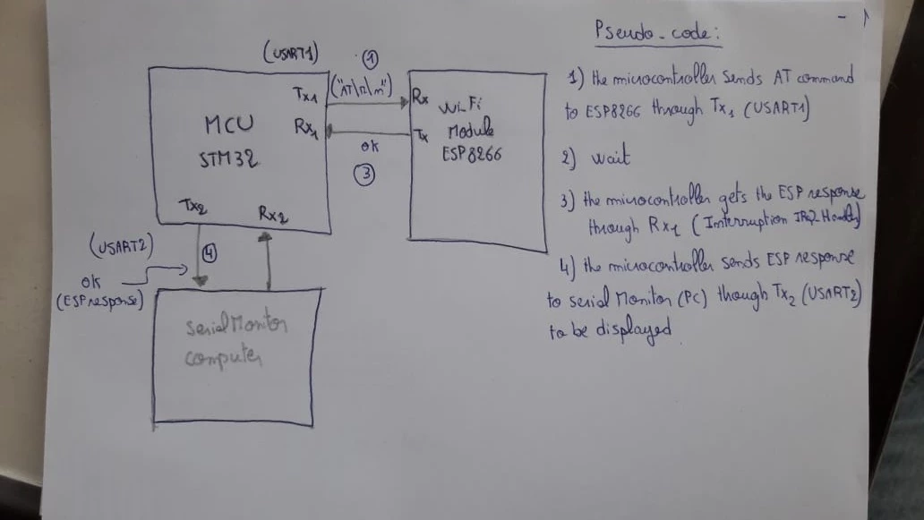
0693W00000BZddpQAD.jpgi'm trying to communicate with a Wifi module (esp8266) using STM32F103, on keil IDE. As described in the schematic : i want making my stm32 send AT command to esp8266 through usart1 (Tx1), and getting the esp response (Rx1), then display the esp response on computer serial monitor using usart2 ( Tx2).

After configuring usart1 and usart2, and writing the functions to send an receive data, i'm getting only the ECHO of the command, rather than the response which should be "OK"

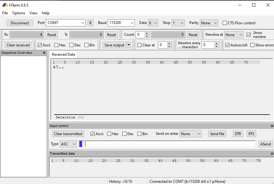
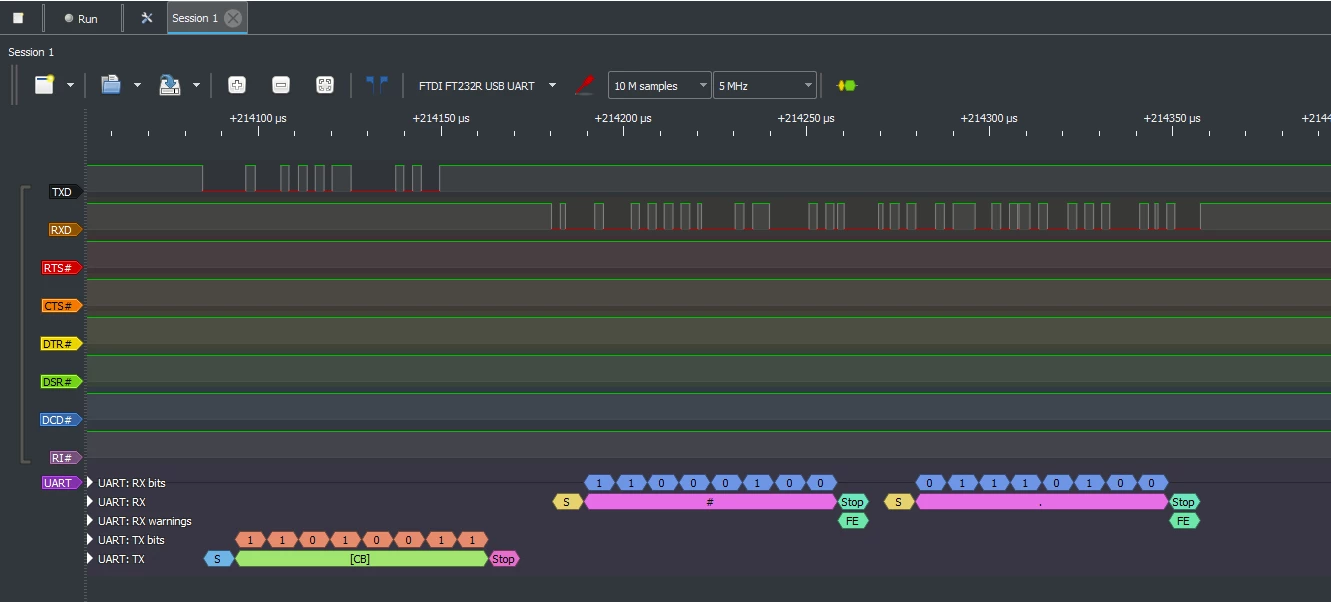
 . when i'm sending "AT\r\n", i'm receiving only AT on serial monitor. i will share the code i have wrote, and the traces on logic analyzer. if there is any suggestion i will be thankful.
0693W00000BZdduQAD.png0693W00000BZde4QAD.png

 int len=0;
char buff[256];
 
int main(void){
 
 __disable_irq();
 
 
 systick_init();
 UART1_Init();
 UART2_Init();
 
 Delayms(100);
 
printMsg1("AT\r\n");
 
 Delayms(100);
 
 NVIC_EnableIRQ(USART1_IRQn);
 
 __enable_irq();
 
while(1){}
 
}
 
 
void USART1_IRQHandler(){
 
if (USART1->SR & USART_SR_RXNE) // if received data (RXNE event flag is set) is ready to be read -->RXNE
 {
 
 buff[len] = USART1->DR;
 
 Delayms(100);
 
 printMsg2(buff);
 
 }
 
}
 
void printMsg1(char *msg, ...) // Sending AT command to ESP ( Stm32-> ESP8266)
{
 
 va_list args;
 va_start(args,msg); 
 vsprintf(buff,msg,args);
 
 for(int i=0;i<strlen(buff);i++)
 {
 
 
 USART1->DR = (buff[i]&0xFF);
 while(!(USART1->SR & USART_SR_TXE)); //wait for TXE, 1 = data transferred
 
 }
}
 
void printMsg2(char *msg, ...) // Sending ESP response to Serial Monitor ( STM32-> PC)
{
 
 va_list args;
 va_start(args,msg); 
 vsprintf(buff,msg,args);
 
 for(int i=0;i<strlen(buff);i++)
 {
 USART2->DR = buff[i];
 while(!(USART2->SR & USART_SR_TXE)); //wait for TXE, 1 = data transferred
 }
}

This topic has been closed for replies.
SIDRI.1
SIDRI.1Best answer
Associate III
Jun 1, 2021 10:35 AM UTC

This is the code modifed : it works fine :

#include "stm32f10x.h" // Device header
#include <stdio.h>
#include "stdint.h"
#include "stdarg.h"
#include "string.h"
#include "Msg_Handle.h"
#include <string.h>
 
 
void UART2_Init(void);
void UART1_Init(void);
void USART1_IRQHandler(void);
void DelayTimerUs(int n);
 
//UART1 --> MCU to Wifi
//UART2 --> MCU to Serial monitor


void UART2_Init(){
	
	//1) Enable USART2 clock and Porta clock (PA2-->Tx & PA3-->Rx)
 
RCC->APB1ENR |= RCC_APB1ENR_USART2EN;
RCC->APB2ENR |= RCC_APB2ENR_IOPAEN;	
 
 
//2) Configuring Tx2 to be used as Alternate function (Special I/O) push-pull output
 
GPIOA->CRL &=~ GPIO_CRL_CNF2_0;
GPIOA->CRL |= GPIO_CRL_CNF2_1;
GPIOA->CRL |= (GPIO_CRL_MODE2_1 | GPIO_CRL_MODE2_0);
	
	
//3) Configuring Rx3 to be used as Alternate function (Special I/O) Float input	
	
	GPIOA->CRL &=~ GPIO_CRL_MODE3_0 | GPIO_CRL_MODE3_1; // 10MHz Rx PA3
	GPIOA->CRL &=~ GPIO_CRL_CNF3_1 ;
	GPIOA->CRL |= GPIO_CRL_CNF3_0;	
	
//3)	Set the Baud rate
 
// USART2->BRR = 0XEA6;					// 9600
 USART2->BRR = 0X138; // 115200
 
//4) CR1 register (Enable usart)
 
	
	USART2->CR1 |= USART_CR1_TE;
 USART2->CR1 |= USART_CR1_RE ;	
 USART2->CR1 |= USART_CR1_UE;
	
}
 
void UART1_Init(){
 
RCC->APB2ENR |= RCC_APB2ENR_IOPAEN | RCC_APB2ENR_AFIOEN | RCC_APB2ENR_USART1EN; //clock to GPIO A enabled, alt.funct.en, USART1 clock enabled
 GPIOA->CRH |= GPIO_CRH_CNF9_1 | GPIO_CRH_MODE9_0 | GPIO_CRH_MODE9_1; //port A9
 GPIOA->CRH &= ~GPIO_CRH_CNF9_0; //port A9 is TX pin
 GPIOA->CRH &= ~(GPIO_CRH_MODE10_0|GPIO_CRH_MODE10_1); //port A10 is RX pin
 GPIOA->CRH |= GPIO_CRH_CNF10_0; //port A10 is RX pin*/
 
USART1->BRR = 0X271; // 115200
	
USART1->CR1 |= USART_CR1_TE;
USART1->CR1 |= USART_CR1_RE ;
USART1->CR1 |= USART_CR1_UE;
 
 USART1->CR1 |= USART_CR1_RXNEIE | USART_CR1_TXEIE ;
	
}
 
void USART1_IRQHandler(){
 
if (USART1->SR & USART_SR_RXNE) // if received data (RXNE event flag is set) is ready to be read -->RXNE
			{
	
		 buff_read[len] = USART1->DR;
 
		 printMsg2(buff_read);
			
 
	}
	
			
}
 
 
int len=0;
char buff[256];
char buff_read[256];
 
void DelayTimerUs(int n){
	// 1 Mhz ---> 1Us
	//ARR = n (n=1 --> 1us) (n=2 --> 2us) ....
 
	RCC->APB1ENR |= RCC_APB1ENR_TIM2EN;
	TIM2->PSC = 36;
	TIM2->ARR = n;
	TIM2->CNT = 0;
	TIM2->CR1 = TIM_CR1_CEN;
	
	for( int i =0; i<n; i++){
		
		 while (!(TIM2->SR & (1<<0))) {}
		}
	TIM2->SR &=~ (1<<0);
		
	TIM2->CR1 &=~ TIM_CR1_CEN;
		
		
	}
 
int main(void){
	
	 __disable_irq();
		
	systick_init();
 UART1_Init();
	UART2_Init();
 
 printMsg1("AT\r\n");
	DelayTimerUs(1000);
	
	printMsg1("AT+RESTORE\r\n");
 DelayTimerUs(1000);
	printMsg1("AT+CWMODE=1\r\n");
	DelayTimerUs(1000);
		
	 NVIC_EnableIRQ(USART1_IRQn);
	
 __enable_irq();
		
while(1){}
 
}
 

9 replies

TDK
May 31, 2021 1:57 PM UTC

I don't see "AT\r\n\" or "OK" in your logic analyzer plot. I do see that it indicates frame errors on the RX line. Doesn't seem like your baud rate matches what the logic analyzer is set to expect.

0693W00000BZghkQAD.png 

Probably not a problem here, but generally you should reverse the order here so it waits for TXE before sending a byte instead of blocking until the transmission is finished.

 USART2->DR = buff[i];
 while(!(USART2->SR & USART_SR_TXE)); //wait for TXE, 1 = data transferred

You're also sending "AT\r\n" without interrupts enabled, so any response is going to get ignored, unless it's sent 100+ms after the message ends.

 __disable_irq();
 ...
 printMsg1("AT\r\n");
 Delayms(100);
 NVIC_EnableIRQ(USART1_IRQn);
 __enable_irq();

"If you feel a post has answered your question, please click ""Accept as Solution""."
SIDRI.1
SIDRI.1Author
Associate III
May 31, 2021 4:24 PM UTC

Thank's for reply,

The baud rate is set at 115200 for stm32, esp8266 and logic analyzer.

I've tried these suggestions, when enabling interrupt then sending "AT\r\n", i get nothing on serial monitor, Rx, Tx are held high (logic analyzer)

TDK
May 31, 2021 5:55 PM UTC

You're saying the values match, but your plot suggests otherwise. Possible your HSE_VALUE is incorrect. Put out a known frequency signal such as MCO on a pin and verify the clock is what you think it is.

"If you feel a post has answered your question, please click ""Accept as Solution""."
SIDRI.1
SIDRI.1Author
Associate III
May 31, 2021 4:24 PM UTC

deleted

Tesla DeLorean
Guru
May 31, 2021 7:42 PM UTC

TXE indicates the buffer is empty, and can take data, you should be FRONT CHECKING it, not back checking

I don't understand the delay in the interrupt, or the non-incrementing buffer pointer, and the use of string, lack of NUL termination, and then reuse of the same buffer in printMsg2

Why can't you do a simple echo of each byte received from USART1 in the IRQ handler to USART2?

Tips, Buy me a coffee, or three.. PayPal Venmo (See Profile) Up vote any posts that you find helpful, it shows what's working..
SIDRI.1
SIDRI.1Author
Associate III
Jun 1, 2021 10:32 AM UTC

it turns out that the "Delayms" function corrupted or caused the losses of the received data , perhaps this is due to the fact that the long waiting time leads to the loss of data.

Furthemore:

 the same buffer is used for sending the AT command and receiving the response "buff[len]", 

which place the receiving data also in buff[len] and seems to be ignored, 

this is why i'm receiving the command echo.

SIDRI.1
SIDRI.1AuthorBest answer
Associate III
Jun 1, 2021 10:35 AM UTC

This is the code modifed : it works fine :

#include "stm32f10x.h" // Device header
#include <stdio.h>
#include "stdint.h"
#include "stdarg.h"
#include "string.h"
#include "Msg_Handle.h"
#include <string.h>
 
 
void UART2_Init(void);
void UART1_Init(void);
void USART1_IRQHandler(void);
void DelayTimerUs(int n);
 
//UART1 --> MCU to Wifi
//UART2 --> MCU to Serial monitor


void UART2_Init(){
	
	//1) Enable USART2 clock and Porta clock (PA2-->Tx & PA3-->Rx)
 
RCC->APB1ENR |= RCC_APB1ENR_USART2EN;
RCC->APB2ENR |= RCC_APB2ENR_IOPAEN;	
 
 
//2) Configuring Tx2 to be used as Alternate function (Special I/O) push-pull output
 
GPIOA->CRL &=~ GPIO_CRL_CNF2_0;
GPIOA->CRL |= GPIO_CRL_CNF2_1;
GPIOA->CRL |= (GPIO_CRL_MODE2_1 | GPIO_CRL_MODE2_0);
	
	
//3) Configuring Rx3 to be used as Alternate function (Special I/O) Float input	
	
	GPIOA->CRL &=~ GPIO_CRL_MODE3_0 | GPIO_CRL_MODE3_1; // 10MHz Rx PA3
	GPIOA->CRL &=~ GPIO_CRL_CNF3_1 ;
	GPIOA->CRL |= GPIO_CRL_CNF3_0;	
	
//3)	Set the Baud rate
 
// USART2->BRR = 0XEA6;					// 9600
 USART2->BRR = 0X138; // 115200
 
//4) CR1 register (Enable usart)
 
	
	USART2->CR1 |= USART_CR1_TE;
 USART2->CR1 |= USART_CR1_RE ;	
 USART2->CR1 |= USART_CR1_UE;
	
}
 
void UART1_Init(){
 
RCC->APB2ENR |= RCC_APB2ENR_IOPAEN | RCC_APB2ENR_AFIOEN | RCC_APB2ENR_USART1EN; //clock to GPIO A enabled, alt.funct.en, USART1 clock enabled
 GPIOA->CRH |= GPIO_CRH_CNF9_1 | GPIO_CRH_MODE9_0 | GPIO_CRH_MODE9_1; //port A9
 GPIOA->CRH &= ~GPIO_CRH_CNF9_0; //port A9 is TX pin
 GPIOA->CRH &= ~(GPIO_CRH_MODE10_0|GPIO_CRH_MODE10_1); //port A10 is RX pin
 GPIOA->CRH |= GPIO_CRH_CNF10_0; //port A10 is RX pin*/
 
USART1->BRR = 0X271; // 115200
	
USART1->CR1 |= USART_CR1_TE;
USART1->CR1 |= USART_CR1_RE ;
USART1->CR1 |= USART_CR1_UE;
 
 USART1->CR1 |= USART_CR1_RXNEIE | USART_CR1_TXEIE ;
	
}
 
void USART1_IRQHandler(){
 
if (USART1->SR & USART_SR_RXNE) // if received data (RXNE event flag is set) is ready to be read -->RXNE
			{
	
		 buff_read[len] = USART1->DR;
 
		 printMsg2(buff_read);
			
 
	}
	
			
}
 
 
int len=0;
char buff[256];
char buff_read[256];
 
void DelayTimerUs(int n){
	// 1 Mhz ---> 1Us
	//ARR = n (n=1 --> 1us) (n=2 --> 2us) ....
 
	RCC->APB1ENR |= RCC_APB1ENR_TIM2EN;
	TIM2->PSC = 36;
	TIM2->ARR = n;
	TIM2->CNT = 0;
	TIM2->CR1 = TIM_CR1_CEN;
	
	for( int i =0; i<n; i++){
		
		 while (!(TIM2->SR & (1<<0))) {}
		}
	TIM2->SR &=~ (1<<0);
		
	TIM2->CR1 &=~ TIM_CR1_CEN;
		
		
	}
 
int main(void){
	
	 __disable_irq();
		
	systick_init();
 UART1_Init();
	UART2_Init();
 
 printMsg1("AT\r\n");
	DelayTimerUs(1000);
	
	printMsg1("AT+RESTORE\r\n");
 DelayTimerUs(1000);
	printMsg1("AT+CWMODE=1\r\n");
	DelayTimerUs(1000);
		
	 NVIC_EnableIRQ(USART1_IRQn);
	
 __enable_irq();
		
while(1){}
 
}
 

Mohamed Aymen HZAMI
ST Employee
Jun 8, 2021 2:10 PM UTC

Hello @SIDRI.1​,

Please mark the helped reply as Best answer (click on "Select as Best"), to help others get the answer quickly.

Mohamed Aymen.