
RTC Time Drift Issue in STM32H743ZIT6
We are developing a project using the STM32H743ZIT6 where RTC timekeeping is a critical requirement. During field testing we noticed significant RTC drift on our board. We tested the same hardware three times — each time flashing a different RCC_LSEDRIVE_* setting to identify which drive level gives the best RTC accuracy. Sharing the full details below test results, firmware, and hardware in case others are facing the same issue.
Quick Results
We ran a 16-hour test measuring RTC drift on the same STM32H743ZIT6 board, flashed three times with a different RCC_LSEDRIVE_* setting each time."
| Drive setting | Drift over ~16 hours | PPM |
|---|---|---|
RCC_LSEDRIVE_LOW | 69 seconds | ~1161 |
RCC_LSEDRIVE_HIGH | 30 seconds | ~519 |
RCC_LSEDRIVE_MEDIUMHIGH | 6 seconds | ~101 |
RCC_LSEDRIVE_MEDIUMHIGH gave the best result by a large margin. RCC_LSEDRIVE_LOW — which is often recommended as the default — gave the worst result on our hardware.
Hardware Details
Crystal
| Parameter | Value |
|---|---|
| MPN | ECS-.327-6-12-TR |
| Frequency | 32.768 kHz |
| Tolerance | ±20 ppm |
| Load cap | 6 pF |
| ESR | 90 kΩ max |
| Package | 2-SMD, No Lead |
Load Capacitors
| Parameter | Value |
|---|---|
| MPN | 0603C0G6R0C500NT |
| Value | 6 pF |
| Voltage | 50V |
| Dielectric | C0G (NP0) — zero temperature coefficient, ideal for crystal circuits |
| Package | 0603 MLCC SMD |
C0G dielectric is the correct choice here — stable across temperature and voltage. This part of the design is sound.
Schematic
The LSE circuit follows the standard two-cap topology:
PC14 (OSC32_IN)→ 0Ω series resistorR5→ crystalY1(ECS-.327-6-12-TR) → 0Ω series resistorR9→PC15 (OSC32_OUT)- Load capacitor
C7(6pF) from OSC32_IN pin to GND - Load capacitor
C10(6pF) from OSC32_OUT pin to GND - Both capacitors are 6PF 50V COG 0603
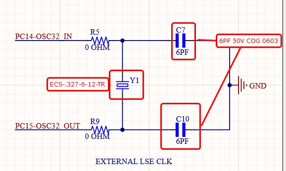
PC14-OSC32_IN  --[R5 0Ω]--+--[C7 6pF]-- GND
                           |
                          [Y1]  ECS-.327-6-12-TR
                           |
PC15-OSC32_OUT --[R9 0Ω]--+--[C10 6pF]-- GND
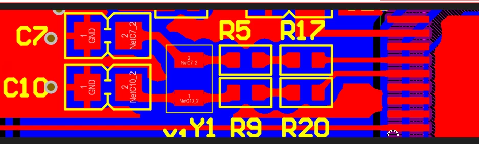
PCB Layout
In the PCB view, the crystal Y1 is placed between the two load capacitors C7 and C10. Series resistors R5 and R9 are placed inline on the OSC32_IN and OSC32_OUT traces respectively.
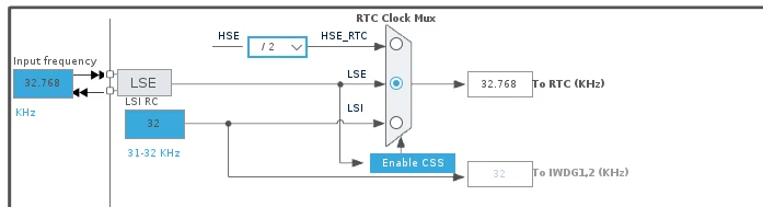
RTC Clock Mux (STM32CubeMX)
As shown in the clock configuration:
- Input: LSE at 32.768 kHz
- RTC Clock Mux: LSE selected (not LSI, not HSE/2)
- Output: 32.768 kHz → To RTC
- LSI RC (31–32 kHz) is present as fallback but not selected for RTC
This is the configuration. LSI would give much worse drift (~1–2%) since it is an internal RC oscillator with no external reference.
Firmware Details
Clock Configuration — SystemClock_Config()
c
void SystemClock_Config(void) {
    RCC_OscInitTypeDef RCC_OscInitStruct = {0};
    RCC_ClkInitTypeDef RCC_ClkInitStruct = {0};

    HAL_PWREx_ConfigSupply(PWR_LDO_SUPPLY);
    __HAL_PWR_VOLTAGESCALING_CONFIG(PWR_REGULATOR_VOLTAGE_SCALE1);
    while (!__HAL_PWR_GET_FLAG(PWR_FLAG_VOSRDY)) {}

    /* Configure LSE Drive Capability */
    HAL_PWR_EnableBkUpAccess();
    __HAL_RCC_LSEDRIVE_CONFIG(RCC_LSEDRIVE_MEDIUMHIGH); // <-- tested at LOW / HIGH / MEDIUMHIGH

    RCC_OscInitStruct.OscillatorType = RCC_OSCILLATORTYPE_HSI48
                                     | RCC_OSCILLATORTYPE_HSI
                                     | RCC_OSCILLATORTYPE_HSE
                                     | RCC_OSCILLATORTYPE_LSE;
    RCC_OscInitStruct.HSEState              = RCC_HSE_ON;
    RCC_OscInitStruct.LSEState              = RCC_LSE_ON;
    RCC_OscInitStruct.HSIState              = RCC_HSI_DIV1;
    RCC_OscInitStruct.HSICalibrationValue   = RCC_HSICALIBRATION_DEFAULT;
    RCC_OscInitStruct.HSI48State            = RCC_HSI48_ON;
    RCC_OscInitStruct.PLL.PLLState          = RCC_PLL_ON;
    RCC_OscInitStruct.PLL.PLLSource         = RCC_PLLSOURCE_HSE;
    RCC_OscInitStruct.PLL.PLLM              = 2;
    RCC_OscInitStruct.PLL.PLLN              = 64;
    RCC_OscInitStruct.PLL.PLLP              = 2;
    RCC_OscInitStruct.PLL.PLLQ              = 4;
    RCC_OscInitStruct.PLL.PLLR              = 2;
    RCC_OscInitStruct.PLL.PLLRGE            = RCC_PLL1VCIRANGE_3;
    RCC_OscInitStruct.PLL.PLLVCOSEL         = RCC_PLL1VCOWIDE;
    RCC_OscInitStruct.PLL.PLLFRACN          = 0;
    HAL_RCC_OscConfig(&RCC_OscInitStruct);

    RCC_ClkInitStruct.ClockType      = RCC_CLOCKTYPE_HCLK | RCC_CLOCKTYPE_SYSCLK
                                     | RCC_CLOCKTYPE_PCLK1 | RCC_CLOCKTYPE_PCLK2
                                     | RCC_CLOCKTYPE_D3PCLK1 | RCC_CLOCKTYPE_D1PCLK1;
    RCC_ClkInitStruct.SYSCLKSource   = RCC_SYSCLKSOURCE_PLLCLK;
    RCC_ClkInitStruct.SYSCLKDivider  = RCC_SYSCLK_DIV1;
    RCC_ClkInitStruct.AHBCLKDivider  = RCC_HCLK_DIV2;
    RCC_ClkInitStruct.APB3CLKDivider = RCC_APB3_DIV2;
    RCC_ClkInitStruct.APB1CLKDivider = RCC_APB1_DIV2;
    RCC_ClkInitStruct.APB2CLKDivider = RCC_APB2_DIV2;
    RCC_ClkInitStruct.APB4CLKDivider = RCC_APB4_DIV2;
    HAL_RCC_ClockConfig(&RCC_ClkInitStruct, FLASH_LATENCY_2);

    HAL_RCC_EnableCSS();
}
Predivider note: AsynchPrediv = 127, SynchPrediv = 255 gives: f_RTC = 32768 / (127+1) / (255+1) = 1 Hz — correct for a 32.768 kHz LSE.
Questions :
- Our hardware uses a 6 pF crystal with 6 pF load caps — but effective CL seen by the crystal includes PCB stray capacitance (typically 1–3 pF per node). Could the mismatch between crystal CL spec and effective board CL be contributing to the higher drift at lower drive levels?
Environment
| Parameter | Value |
|---|---|
| MCU | STM32H7 series |
| HAL | STM32CubeH7 |
| Crystal | ECS-.327-6-12-TR (32.768 kHz, 6pF) |
| Load capacitors | 0603C0G6R0C500NT (6pF, C0G, 0603) |
| Series resistors | 0Ω (R5, R9) |
| RTC clock source | LSE (selected in clock mux) |
| AsynchPrediv | 127 |
| SynchPrediv | 255 |
| Power supply | LDO (PWR_LDO_SUPPLY) |
| Voltage scaling | Scale 1 |
| Test duration | ~16 hours per measurement |
Happy to share more log data or PCB details if useful. Any input from teams who have done long-term RTC accuracy work on STM32H7 is appreciated.