Associate II
April 16, 2021
Solved
Right edge aligned PWM
- April 16, 2021
- 6 replies
- 2048 views
I've edited this post to make it more useful to others.
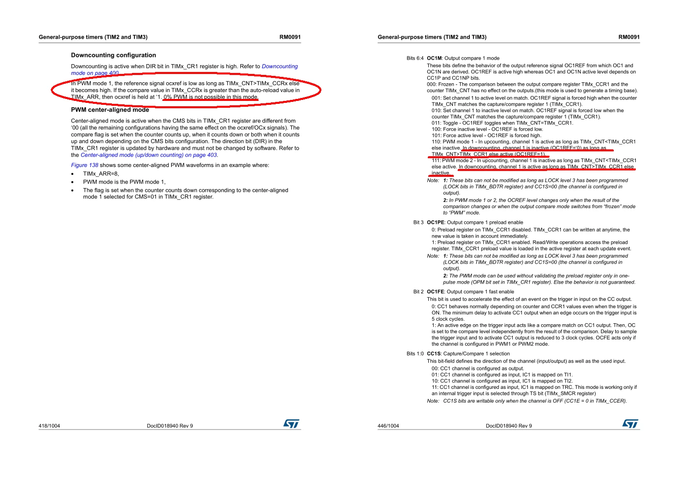
We are well into development of a board at work using an STM32F072RBT6 MCU. I just wrote a quick from scratch test using a NUCLEO-F072RB board to verify things. I'm not sure of the exact problem, but it appears TIM2 is adding 1 to the CCR. I have the timer configured that each count is 1 us, using PWM mode 1, and down-counting. If I write in a CCR of 0, I get a 1 us pulse. If I write in a CCR of 1, I get a 2 us pulse. If I write in a CCR of 2, I get 3 us pulse. You get the picture. I attached the demo project as a zip. I also setup TIM1, but used up-counting and it works as expected. main.c has some comments in it.