Kye-Hyun Park
Associate II
November 21, 2017
Solved

Regarding ADC input source on STM32F3Discovery board

  • November 21, 2017
  • 14 replies
  • 19743 views
Posted on November 21, 2017 at 13:27

Dear All,

I'd like to test an ADC conversion using ADC example from STM32F3Discovery's peripheral examples.

I connected ADC1 channel(PC1) and GND to external power supply directly. and It was measured anormalvoltage between PC1 and GND using FLUKE Multimeter 8846A.

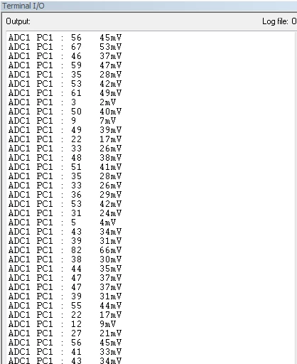
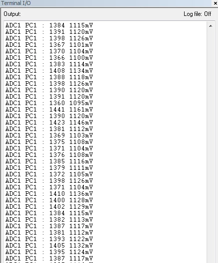
But, as attached the ADC value on Terminal I/O, theresults are very unstable. Is that due to the bad connection for ADC input source? or I cannot catch the problem exactly. Could you please help the issue?

1. supplying 0V to ADC1 channel(PC1)

0690X0000060PFEQA2.png

2. supplying 1.0V to ADC1 channel(PC1)

0690X0000060PFFQA2.png

    This topic has been closed for replies.
    Best answer by Reynoso.Salvador
    Posted on November 22, 2017 at 03:44

    It could be induced noise from your multimeter. You can filter your signal adding a RC filter to the ADC input.

    14 replies

    AvaTar
    Senior III
    November 21, 2017
    Posted on November 21, 2017 at 13:49

      /* ADC1 regular channel3 configuration */

      ADC_RegularChannelConfig(ADC1, ADC_Channel_7, 1, ADC_SampleTime_7Cycles5);

    I suggest to try a much longer sample time.

    Like ADC_SampleTime_181Cycles5 or ADC_SampleTime_601Cycles5.

    Kye-Hyun Park
    Associate II
    November 21, 2017
    Posted on November 21, 2017 at 14:23

    Thank you for your reply.

    I tried a much longer sampling time with ADC_SampleTime_601Cycles5 but, it is still unstable.

    AvaTar
    Senior III
    November 21, 2017
    Posted on November 21, 2017 at 15:47

    ... it is still unstable.

    How much ?

    The F3 discovery is not quite the best analog design, Vdda and Vref on the Disco is connected to Vdd (the digital supply), so you can't expect too much.

    Does the input impedance of your source match, and how long are the wires ?

    Uwe Bonnes
    Chief
    November 21, 2017
    Posted on November 21, 2017 at 23:17

    Do some statistics. What is the RMS error?

    Kye-Hyun Park
    Associate II
    November 22, 2017
    176119CGIL2
    Reynoso.Salvador
    Reynoso.SalvadorBest answer
    Visitor II
    November 22, 2017
    Posted on November 22, 2017 at 03:44

    It could be induced noise from your multimeter. You can filter your signal adding a RC filter to the ADC input.

    Kye-Hyun Park
    Associate II
    November 22, 2017
    Posted on November 22, 2017 at 11:59

    Thank you, ADC conversion result is stable after adding RC filter (1kohm, 0.1uF).

    FYI, The Cut-off frequency Fc is 1591.549430919Hz with R=1kohm, C=0.1uF from 

    http://sim.okawa-denshi.jp/en/CRtool.php

     .

    The problem has disappeared, but I wonder why high-frequency noise was induced to ADC input line.

    AvaTar
    Senior III
    November 22, 2017
    Posted on November 22, 2017 at 13:12

    Shorter, and shielded/twisted wiring would probably have helped, too.

    I use to test my ADC implementations with a battery, and wires no longer than 5..10cm.

    PeterJ
    Associate
    November 23, 2017
    Posted on November 23, 2017 at 11:30

    You could also set HW oversampling to 16 or higher, this will also give a low pass / averaging of your signal.

    You then have 2 choices:

    You can use the build-in shift function to divide by 2, 4, 8, 16 or ...

    Or you can use the adc value as it is (all the samples are added in HW so it only requires the setup and are read as if you are making one simple sample) and divide by the number of oversamples you do, this will give you the best resolution.

    Remember to that the variable might be set as half word which means that if you add 16 samples of 4095, this i the maximum value of a half word.

    Using e.g 32 times oversampling you can shift the result right 1 place (also setup in adc settings and will be automatically done without any additional code).

    David.Yves
    Associate
    November 23, 2017
    Posted on November 23, 2017 at 14:07

    Your results may not be as bad as you think. With 0V applied the largest deviation is 45mV  or 1.5% of full scale(3V). Your voltmeter will read between 2% to 5% of full scale depending on make and model. This is very good performance for your design. 

    The second set of reading show an offset of +0.1 or 10% of the applied test voltage this can be due to the source you are using ( power supply, voltage divider ...) . I will assume that you have verified the math to convert from ADC output  value  to mV.

    To verify the performance of your ADC use a fresh battery single cell ( Duracell alcaline will read 16xx mV)

    I don't know your application but if you require more precision you can use an op amp to boost the signal making the radiated and conducted noise less relevant.

    AvaTar
    Senior III
    November 23, 2017
    Posted on November 23, 2017 at 14:17

    Your results may not be as bad as you think. With 0V applied the largest deviation is 45mV  or 1.5% of full scale(3V). .... This is very good performance for your design.

    I beg to disagree on this one.

    Shorting the ADC input as close as possible to the input should yield a zero result reading, give one LSB.

    A 45mV reading suggests noise, i.e. the sample cap picked up a substantial charge through long wiring and improper impedance.