christophe onillon
Associate II
December 8, 2016
Question

Re: connect X-NUCLEO-IDB04A1 to stm32f746g discovery -> Adding support to the packages

  • December 8, 2016
  • 6 replies
  • 1555 views
Posted on December 08, 2016 at 15:35

about

https://community.st.com/0D50X00009XkeG3SAJ

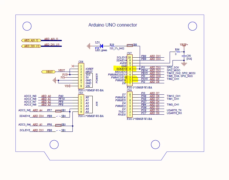
OK for the idea, a small rework to do on the board in this case.

1- i need to disable the pin 13 mangement in the application (BSP_LED) in stm32f746g_discovery.c file in the demonstration project of the board.

what is the default state of the pins if not initialize, please ?

2- Create a new configuration for the spi2 (using for example stm32 cube) with d13,d12,d11 clk, mosi, miso pins.

the base of the configuration that can be found on the projet in the stm32f4x_nucleo.c file

And add a new entry in the stm32_blue_nrg_ble.h file and complete stm32f746g_discovery file.

i didn't find the ico extension file  wih the démonstrations to modify the configuration.

Is there a possibility to reverse the ioc file ?

3- create a new entry in the stm32bluenrg_ble.h adding support for this board.

i hope that i'll not lost functionnality about pin affected to spi2 : the goal is to keep all current demo and add ble scanner for example.

Your advice ?
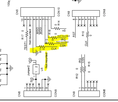
0690X00000605kxQAA.png0690X00000605auQAA.png

null
    This topic has been closed for replies.

    6 replies

    Antonio Vilei
    ST Employee
    December 9, 2016
    Posted on December 09, 2016 at 18:32

    Hi Christophe,

    from which source project did you start for the DISCO-F746NG board? Is it the demo code included in the STM32CubeF7 package? That would help me understand what is the best course of action in your case. Which IDE are you using for building?

    What kind of project are you working on? Are you planning to build a product out of it or is it for demo purposes?

    As for the .ioc configuration file, it is not available yet for the BLE examples included in the X-CUBE-BLE1 software expansion package, but I'll build one for you as soon as possible. Meanwhile, besides creating an entry for your Discovery board in the stm32_bluenrg_ble.h file, you should also create a new file in the BSP directory for the Discovery. As a starting point you could use the

    Drivers\BSP\STM32F4xx-Nucleo\stm32f4xx_nucleo_bluenrg.h file that is configured for NUCLEO-F401RE.

    Best regards,

    Antonio

    christophe onillon
    Associate II
    December 9, 2016
    Posted on December 09, 2016 at 20:49

    Hi Antonio,

    i found a case

    http://www.iwasz.pl/uncategorized/bluenrg-stm32f7-disco-tests/

     where is a first configuration.

    i propose you in a first step to realize the configuration of the spi 2 (with screenshot) and synchronize with you.

    it's a good challenge to learn and i think usefull to your package so follow me ;->>

    i'll begin with the pin configuration.

    christophe onillon
    Associate II
    December 9, 2016
    Posted on December 09, 2016 at 21:46

    well ... using stm32cubemx we obtain :

    0690X00000605p3QAA.png

    and the device configuration (limited spedd to ensure to have a compatible speed):

    0690X00000605p8QAA.png

    we obtain spi initialisation

    hspi2.Init.Mode = SPI_MODE_MASTER;

    hspi2.Init.Direction = SPI_DIRECTION_2LINES;

    hspi2.Init.DataSize = SPI_DATASIZE_8BIT;

    hspi2.Init.CLKPolarity = SPI_POLARITY_LOW;

    hspi2.Init.CLKPhase = SPI_PHASE_1EDGE;

    hspi2.Init.NSS = SPI_NSS_SOFT;

    hspi2.Init.BaudRatePrescaler = SPI_BAUDRATEPRESCALER_128;

    hspi2.Init.FirstBit = SPI_FIRSTBIT_MSB;

    hspi2.Init.TIMode = SPI_TIMODE_DISABLE;

    hspi2.Init.CRCCalculation = SPI_CRCCALCULATION_DISABLE;

    hspi2.Init.CRCPolynomial = 7;

    hspi2.Init.CRCLength = SPI_CRC_LENGTH_DATASIZE;

    hspi2.Init.NSSPMode = SPI_NSS_PULSE_ENABLE;

     and spi pin setup :

    0690X00000605mPQAQ.png

    and pins configurations:

    GPIO_InitStruct.Pin = ARDUINO_SCK_D13_Pin;

    GPIO_InitStruct.Mode = GPIO_MODE_AF_PP;

    GPIO_InitStruct.Pull = GPIO_PULLDOWN;

    GPIO_InitStruct.Speed = GPIO_SPEED_FREQ_HIGH;

    GPIO_InitStruct.Alternate = GPIO_AF5_SPI2;

    HAL_GPIO_Init(ARDUINO_SCK_D13_GPIO_Port, &GPIO_InitStruct);

    GPIO_InitStruct.Pin = ARDUINO_MISO_D12_Pin|ARDUINO_MOSI_PWM_D11_Pin;

    GPIO_InitStruct.Mode = GPIO_MODE_AF_PP;

    GPIO_InitStruct.Pull = GPIO_NOPULL;

    GPIO_InitStruct.Speed = GPIO_SPEED_FREQ_HIGH;

    GPIO_InitStruct.Alternate = GPIO_AF5_SPI2;

    HAL_GPIO_Init(GPIOB, &GPIO_InitStruct);

    enabling interrupt:

    0690X00000605pIQAQ.png