

Question on SPI communication
Hi
I am learning to write driver code for SPI. I have an nucleo-L476RG development board with me implementing full-duplex transmit only operation and reading the output of a MOSI pin using a logic-analyzer. The Nucleo board is working as the master
So far this is my understanding of the SPI based on the reference manual.
- 2 x 32-bit FIFO buffers one for Rx and One for Tx
- The number of data that can be transmitted : 4 bits - 16 bits, it can be configured in the CR2-> DS register of the respective peripheral
- When the data < 8 bits the data is packed to 8 bits, when the 8< data < 16 bits the data is packed to 16 bits
SPI Parameters
SPI Peripheral - SPI1
Clock Frequency - 4 MHz
Baud Rate - SYS_CLK_DIV_64
CPHA - First Clock Edge
CPOL - Zero when Idle
LSB First - Data transmitted with MSB first
Data Size - 8 bits per frame
Communication Mode - Full duplex(BIDIMODE:0, BIDIOE:0, RXONLY: 0)
Software Slave Management - Enabled
Internal Slave Select -1
Device Mode - Master
GPIO Pin Configuration
GPIO A, Pin 5 -SPI CLK
PinMode - Alternate Function
Alternate function Mode - AF5
Output Type - Push-Pull
GPIO Speed - Default - Not configured
GPIO A, Pin 6 - SPI_MISO
PinMode - Alternate Function
Alternate function Mode - AF5
Output Type - Push-Pull
GPIO Speed - Default - Not configured
GPIO A, Pin 7 - SPI_MOSI
PinMode - Alternate Function
Alternate function Mode - AF5
Output Type - Push-Pull
GPIO Speed - Default - Not configured
GPIO A, Pin 4 - SPI_NSS
PinMode - Alternate Function
Alternate function Mode - AF5
Output Type - Push-Pull
GPIO Speed - Default - Not configured
Output from logic analyzer:
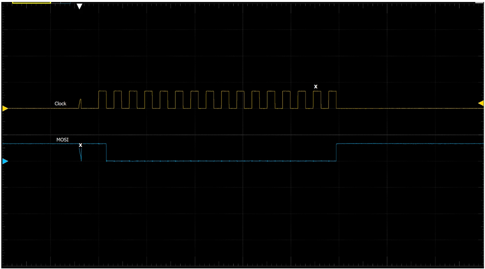
Case: 1 Data transferred: 0x1
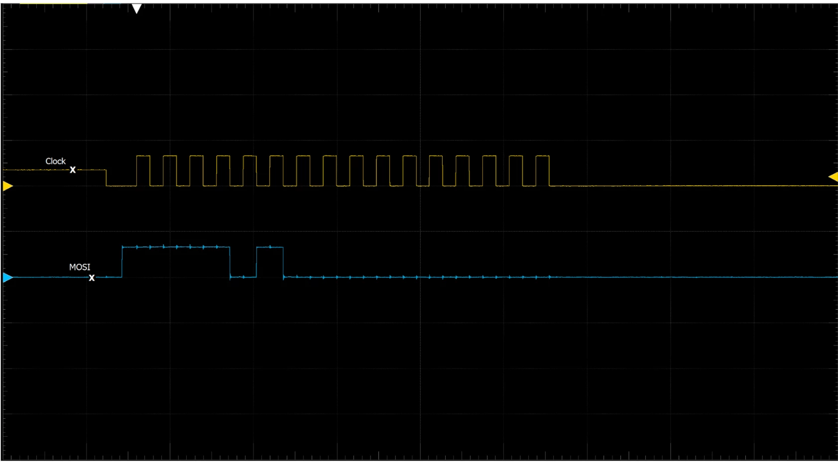
 Case :2 Data Transferred : 0x2F, Data Size(DS= 4)
 I have implemented the blocking call for SPI so far in my logic,
Questions:
- In Case-1 I have set the DS size to 8 bits and my data is also of uint8_t why then is 16 clocks sent from the master?
- In Case-2 when the DS is set to 4 bits why are the bits after 4 bits sent(binary of 0x2F is 0010 1111)?
- I have not configured the Pin speed of the pin in the GPIO configuration, is it necessary to configure it as the High speed?
- I have an another case which is not documented here, say I have an slave which will reply back with a value(16-bit) based the address represented by 4 bits of the MOSI, in this case how should the clock be configured to output 8+16 clocks to successfully transact the information

