


uilter
Senior
July 5, 2023
Solved

QSPI - Read UNIQUE ID from W25Qxx NOR memory

  • July 5, 2023
  • 14 replies
  • 15212 views

Hi ST community!

I'm a liltle confused about how to read the UNIQUE ID from memory NOR W25Qxx. In my case a use the W25Q128 - https://www.winbond.com/hq/product/code-storage-flash-memory/serial-nor-flash/?__locale=en&partNo=W25Q128JV

We already use this memory in another custom boards.
We able to flash, create external loaders and use it with touchgfx.

This custom board has a STM32H753.

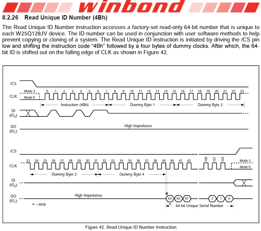
I want to understand the correct way to read this instruction UNIQUE ID (4Bh). To get this value, the datasheet says after the INSTRUCTION (4Bh) I need to add 4 bytes of DUMMY clock (32 clocks). After this, I will able to receive the 64 bits from the UNIQUE ID.
uilter_0-1688522617046.png

I'm a little confused about my tests and would like some help from the community to know if some of the two paths I show below are correct or none of them haha


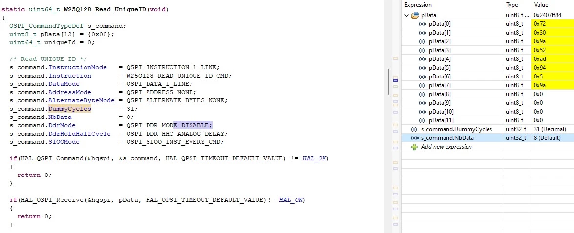
1) My first try was using the code below, but I always get corrupt data.
- I put the max dummy cycles allowed (31). Check it on the HAL lib and reference manual.
- read 8 bytes (64 bits from the UNIQUE ID)
uilter_0-1688526470865.png

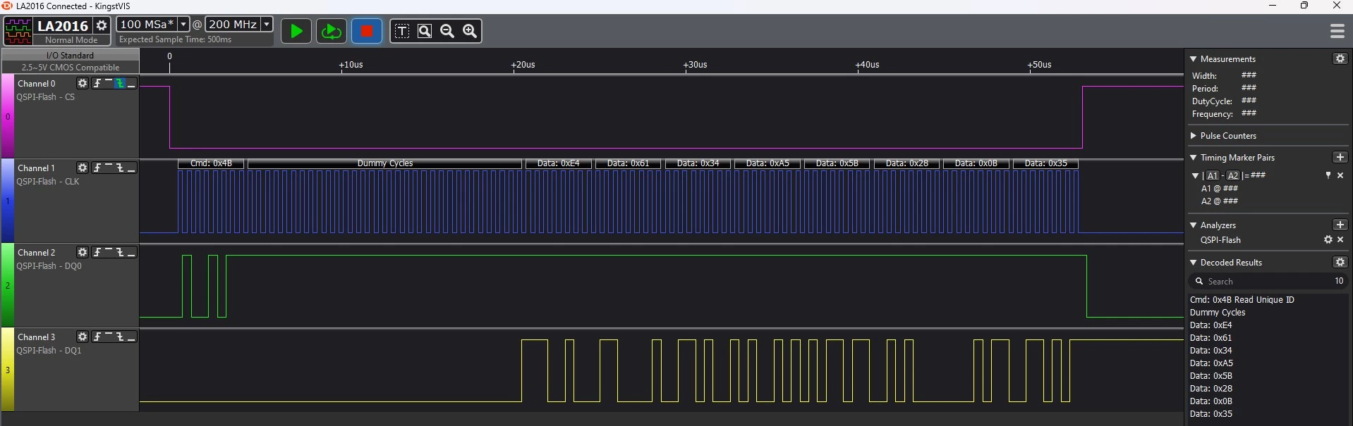
Looking the logic analyzer, I figure out the data is shifted to left. The last byte was not readed.
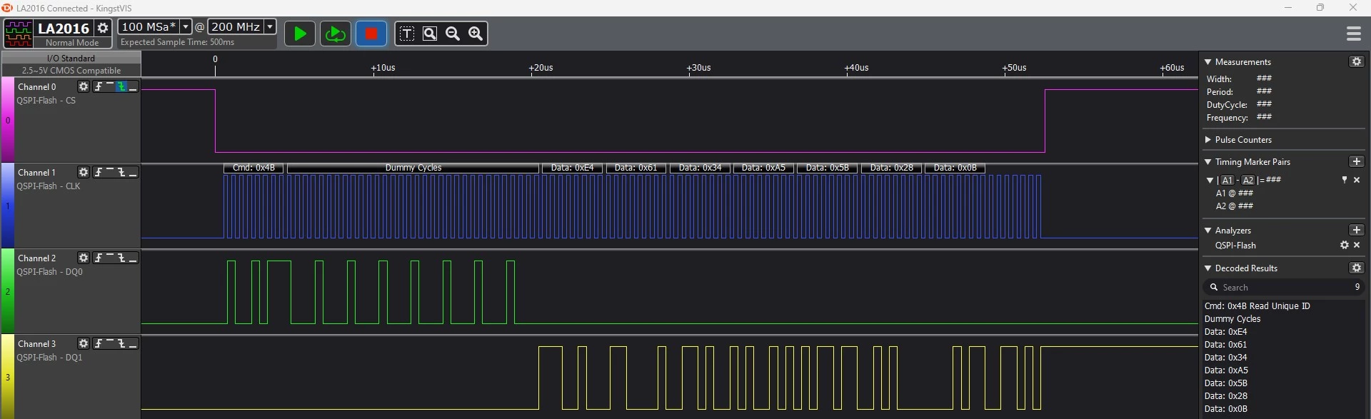
uilter_1-1688526540478.png

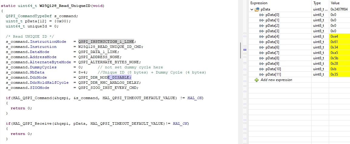
2) The second try was the code bellow:
- I sum the 8 bytes from UNIQUE ID with the Dummy bytes. 
- the first 4 bytes are zero and the UNIQUE ID start at index 4 in pData array.
uilter_2-1688526686011.png

Looking the logic analyzer, the data is fine.
uilter_3-1688526720463.png

Please, anyone can advise me the correct way to read this UNIQUE ID from W25Q128 NOR memory?

Many thanks!
This topic has been closed for replies.
Best answer by uilter

We did tests in 3 different boads. All custom boards has this memory (W25Q128xx).
The difference between this board is the MCU: STM32H753BI, 753II and 753ZI.

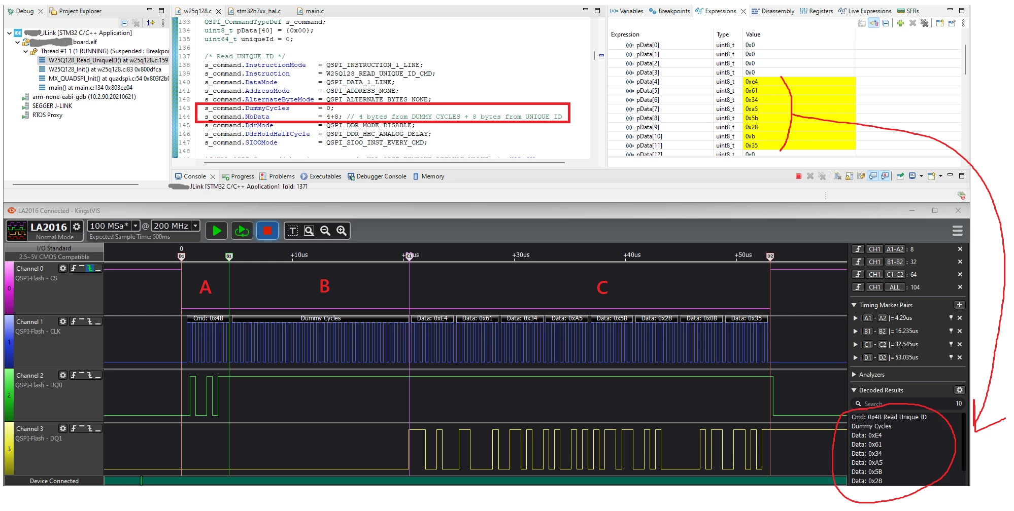
The following image show the code to read this UNIQUE ID and bellow the logic analyzer.
You can see the debug mode, the array pData match with the logic analyzer.

uilter_0-1688572708083.png

We setup the logic analyzer adding time markers and a counter in CLOCK line of the QSPI.
According the datasheet, we need in total 104 clocks, splitted in:
- A marker, 8 clocks: instruction (4Bh)
- B marker, 32 clocks: dummy cycles
- C marker, 64 clocks: 64-bits UNIQUE ID
- D marker, total of 104 clocks. This match with Figure 42 wave form in W25Q128 datasheet.

Whatever is the value for variable s_command.DummyCycles, I not able to see a different behaviour on my logic analyzer even in the oscilloscope...

We test it on 3 different custom boards, as I mentioned. The MSB byte 0xE4 always repeat. The rest of pData value is different. Putting the logic analyzer on it, the value matches with Data.

14 replies

ST Technical Moderator
July 5, 2023

Hello @uilter,


Some updates in the configuration should be adjusted:

s_Command.DummyCycles = 4; //according to the datasheet

s_Command.NbData      = 8; // 64bits

If still facing issues, please keep me updated!
 

To give better visibility on the answered topics, please click on "Best answer" on the reply which solved your issue or answered your question.Best regards,FBL
uilter
uilterAuthor
Senior
July 5, 2023

Hi @FBL , thanks for your reply!

We test according your suggestion, but not works. This is my output.

uilter_1-1688573334754.png


jumman_JHINGA
Senior III
July 5, 2023

Im also facing QUADSPI issue with touchGFX... in my case TouchGFX Background image is getting saved into QSPI memory... im also using W25Q128 ic for storing ... but whatever data is getting saved on QSPI is not getting displayed on Display.. but Those data who are getting saved into flash memory is getting displayed properly.


and more thing is ... when i used STemwin for same configuration every thing is getting displayed properly :thinking_face:

raptorhal2
Lead
July 5, 2023

It would be much clearer if everyone used s_command.DummyBytes.

raptorhal2
Lead
July 5, 2023

And if s_command.NbData was s_command.NBytesData.

And if I could edit my post.

uilter
uilterAuthorBest answer
Senior
July 5, 2023

We did tests in 3 different boads. All custom boards has this memory (W25Q128xx).
The difference between this board is the MCU: STM32H753BI, 753II and 753ZI.

The following image show the code to read this UNIQUE ID and bellow the logic analyzer.
You can see the debug mode, the array pData match with the logic analyzer.

uilter_0-1688572708083.png

We setup the logic analyzer adding time markers and a counter in CLOCK line of the QSPI.
According the datasheet, we need in total 104 clocks, splitted in:
- A marker, 8 clocks: instruction (4Bh)
- B marker, 32 clocks: dummy cycles
- C marker, 64 clocks: 64-bits UNIQUE ID
- D marker, total of 104 clocks. This match with Figure 42 wave form in W25Q128 datasheet.

Whatever is the value for variable s_command.DummyCycles, I not able to see a different behaviour on my logic analyzer even in the oscilloscope...

We test it on 3 different custom boards, as I mentioned. The MSB byte 0xE4 always repeat. The rest of pData value is different. Putting the logic analyzer on it, the value matches with Data.

ST Technical Moderator
July 6, 2023

Hello again @uilter 

Could you keep the receive buffer size 8 and empty uint8_t pData[8] = {}.

To give better visibility on the answered topics, please click on "Best answer" on the reply which solved your issue or answered your question.Best regards,FBL
uilter
uilterAuthor
Senior
July 6, 2023

Hi @FBL , this is the result:

uilter_0-1688658536765.png


uilter
uilterAuthor
Senior
July 6, 2023

Hi @Tesla DeLorean thanks to join us.

In your experience, the way I'm reading the UNIQUE ID register is correct? Read 12 bytes, discard the first 4 bytes and consider the rest of the array.

Thanks.

Tesla DeLorean
Guru
July 7, 2023

Staging in a buffer, and copying out would be the way I'd go.

For other "unique" values you could use the Security Registers, and protect via OTP setting in the status registers. Other parts have OTP, the Micron parts have unique data / serialization deeper into the JEDEC ID (0x9F)

Tips, Buy me a coffee, or three.. PayPal Venmo (See Profile) Up vote any posts that you find helpful, it shows what's working..
uilter
uilterAuthor
Senior
July 8, 2023

@Tesla DeLorean thanks for your contribution and tips for others solutions.

ST Technical Moderator
July 7, 2023

Well, your second try was correct. In the dummy-cycle phase, the microcontroller can allocate a maximum 31 cycles, however the memory needs 32 cycles to process the read ID.

FBelaid_0-1688720099199.png

Here is another option you can consider.

s_Command.DummyCycles = 31; //31 bits of dummy cycles

s_Command.NbData      = 8+1; // 8 bytes of data + 1byte as dummy

To give better visibility on the answered topics, please click on "Best answer" on the reply which solved your issue or answered your question.Best regards,FBL
uilter
uilterAuthor
Senior
July 8, 2023

@FBL thanks to confirm the quantity of dummy cycles.

I'll use my second try. Thanks for your support here.