

ROlii.1
Associate
April 15, 2022
Solved

QSPI from Dual to Single flash mode

Hello, I tried to start QSPI working on a Single flash mode but have a problem with non readable part config registers (NonVolatile, Volatile and Enhanced Volatile). As I understand when working in Dual Flash mode this registers should write and read in pairs, but I receive this weird data(the screen below). In Single flash mode all registers have only 0x55. The question is:

  1. How to wake up the second chip of external flash memory?
  2. What are the right configurations for Single flash mode?

The microcontroller is STM32H750B-DK and external memory MT25QL512ABB0693W00000Ly4hwQAB.png
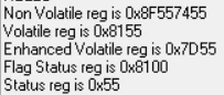
This topic has been closed for replies.
Tesla DeLorean
Tesla DeLoreanBest answer
Guru
April 15, 2022

The BOARD is STM32H750B-DK, the MCU is STM32H750XBH6

Will come down to initialization code, which you don't show.

The two chips share a common chip select, but the second one is the QSPI BK2 data pins.

You should be able to read a byte if dual mode is disabled, and you use QSPI_FLASH_ID_1

Tips, Buy me a coffee, or three.. PayPal Venmo (See Profile) Up vote any posts that you find helpful, it shows what's working..

2 replies

Tesla DeLorean
Tesla DeLoreanBest answer
Guru
April 15, 2022

The BOARD is STM32H750B-DK, the MCU is STM32H750XBH6

Will come down to initialization code, which you don't show.

The two chips share a common chip select, but the second one is the QSPI BK2 data pins.

You should be able to read a byte if dual mode is disabled, and you use QSPI_FLASH_ID_1

Tips, Buy me a coffee, or three.. PayPal Venmo (See Profile) Up vote any posts that you find helpful, it shows what's working..
ROlii.1
ROlii.1Author
Associate
April 18, 2022

This register read is from dual-flash config. This is the initialization code:

void MX_QUADSPI_Init(void)
{
 
 /* USER CODE BEGIN QUADSPI_Init 0 */
 
 /* USER CODE END QUADSPI_Init 0 */
 
 /* USER CODE BEGIN QUADSPI_Init 1 */
 
 /* USER CODE END QUADSPI_Init 1 */
 hqspi.Instance = QUADSPI;
 hqspi.Init.ClockPrescaler = 1;
 hqspi.Init.FifoThreshold = 1;
 hqspi.Init.SampleShifting = QSPI_SAMPLE_SHIFTING_NONE;
 hqspi.Init.FlashSize = 19;
 hqspi.Init.ChipSelectHighTime = QSPI_CS_HIGH_TIME_4_CYCLE;
 hqspi.Init.ClockMode = QSPI_CLOCK_MODE_0;
//#ifdef FLASHID
// hqspi.Init.FlashID = QSPI_FLASH_ID_1;
//#else
 hqspi.Init.FlashID = QSPI_FLASH_ID_1;
//#endif
 hqspi.Init.DualFlash = QSPI_DUALFLASH_ENABLE;
 if (HAL_QSPI_Init(&hqspi) != HAL_OK)
 {
 Error_Handler();
 }
 /* USER CODE BEGIN QUADSPI_Init 2 */
 
 /* USER CODE END QUADSPI_Init 2 */
 
}
 
void HAL_QSPI_MspInit(QSPI_HandleTypeDef* qspiHandle)
{
 
 GPIO_InitTypeDef GPIO_InitStruct = {0};
 RCC_PeriphCLKInitTypeDef PeriphClkInitStruct = {0};
 if(qspiHandle->Instance==QUADSPI)
 {
 /* USER CODE BEGIN QUADSPI_MspInit 0 */
 
 /* USER CODE END QUADSPI_MspInit 0 */
 /** Initializes the peripherals clock
 */
 PeriphClkInitStruct.PeriphClockSelection = RCC_PERIPHCLK_QSPI;
 PeriphClkInitStruct.QspiClockSelection = RCC_QSPICLKSOURCE_D1HCLK;
 if (HAL_RCCEx_PeriphCLKConfig(&PeriphClkInitStruct) != HAL_OK)
 {
 Error_Handler();
 }
 /* QUADSPI clock enable */
 __HAL_RCC_QSPI_CLK_ENABLE();
 
 __HAL_RCC_GPIOG_CLK_ENABLE();
 __HAL_RCC_GPIOF_CLK_ENABLE();
 __HAL_RCC_GPIOD_CLK_ENABLE();
 /**QUADSPI GPIO Configuration
 PG6 ------> QUADSPI_BK1_NCS
 PF6 ------> QUADSPI_BK1_IO3
 PF7 ------> QUADSPI_BK1_IO2
 PF10 ------> QUADSPI_CLK
 PF9 ------> QUADSPI_BK1_IO1
 PD11 ------> QUADSPI_BK1_IO0
 */
 GPIO_InitStruct.Pin = GPIO_PIN_6;
 GPIO_InitStruct.Mode = GPIO_MODE_AF_PP;
 GPIO_InitStruct.Pull = GPIO_NOPULL;
 GPIO_InitStruct.Speed = GPIO_SPEED_FREQ_LOW;
 GPIO_InitStruct.Alternate = GPIO_AF10_QUADSPI;
 HAL_GPIO_Init(GPIOG, &GPIO_InitStruct);
 
 GPIO_InitStruct.Pin = GPIO_PIN_6|GPIO_PIN_7|GPIO_PIN_10;
 GPIO_InitStruct.Mode = GPIO_MODE_AF_PP;
 GPIO_InitStruct.Pull = GPIO_NOPULL;
 GPIO_InitStruct.Speed = GPIO_SPEED_FREQ_LOW;
 GPIO_InitStruct.Alternate = GPIO_AF9_QUADSPI;
 HAL_GPIO_Init(GPIOF, &GPIO_InitStruct);
 
 GPIO_InitStruct.Pin = GPIO_PIN_9;
 GPIO_InitStruct.Mode = GPIO_MODE_AF_PP;
 GPIO_InitStruct.Pull = GPIO_NOPULL;
 GPIO_InitStruct.Speed = GPIO_SPEED_FREQ_LOW;
 GPIO_InitStruct.Alternate = GPIO_AF10_QUADSPI;
 HAL_GPIO_Init(GPIOF, &GPIO_InitStruct);
 
 GPIO_InitStruct.Pin = GPIO_PIN_11;
 GPIO_InitStruct.Mode = GPIO_MODE_AF_PP;
 GPIO_InitStruct.Pull = GPIO_NOPULL;
 GPIO_InitStruct.Speed = GPIO_SPEED_FREQ_LOW;
 GPIO_InitStruct.Alternate = GPIO_AF9_QUADSPI;
 HAL_GPIO_Init(GPIOD, &GPIO_InitStruct);
 
 /* USER CODE BEGIN QUADSPI_MspInit 1 */
 __HAL_RCC_GPIOC_CLK_ENABLE();
 __HAL_RCC_GPIOH_CLK_ENABLE();
 /**QUADSPI GPIO Configuration
 PG9 ------> QUADSPI_BK2_IO2
 PG14 ------> QUADSPI_BK2_IO3
 PF10 ------> QUADSPI_CLK
 PH2 ------> QUADSPI_BK2_IO0
 PH3 ------> QUADSPI_BK2_IO1
 */
 GPIO_InitStruct.Pin = GPIO_PIN_9|GPIO_PIN_14;
 GPIO_InitStruct.Mode = GPIO_MODE_AF_PP;
 GPIO_InitStruct.Pull = GPIO_NOPULL;
 GPIO_InitStruct.Speed = GPIO_SPEED_FREQ_LOW;
 GPIO_InitStruct.Alternate = GPIO_AF9_QUADSPI;
 HAL_GPIO_Init(GPIOG, &GPIO_InitStruct);
 
 GPIO_InitStruct.Pin = GPIO_PIN_10;
 GPIO_InitStruct.Mode = GPIO_MODE_AF_PP;
 GPIO_InitStruct.Pull = GPIO_NOPULL;
 GPIO_InitStruct.Speed = GPIO_SPEED_FREQ_LOW;
 GPIO_InitStruct.Alternate = GPIO_AF9_QUADSPI;
 HAL_GPIO_Init(GPIOF, &GPIO_InitStruct);
 
 GPIO_InitStruct.Pin = GPIO_PIN_2|GPIO_PIN_3;
 GPIO_InitStruct.Mode = GPIO_MODE_AF_PP;
 GPIO_InitStruct.Pull = GPIO_NOPULL;
 GPIO_InitStruct.Speed = GPIO_SPEED_FREQ_LOW;
 GPIO_InitStruct.Alternate = GPIO_AF9_QUADSPI;
 HAL_GPIO_Init(GPIOH, &GPIO_InitStruct);
 
 
 // Reset the QuadSPI memory interface 
 __HAL_RCC_QSPI_FORCE_RESET();
 __HAL_RCC_QSPI_RELEASE_RESET();
 
 // NVIC configuration for QSPI interrupt
 HAL_NVIC_SetPriority(QUADSPI_IRQn, 0x0F, 0);
 HAL_NVIC_EnableIRQ(QUADSPI_IRQn);
 /* USER CODE END QUADSPI_MspInit 1 */
 }
}

