Floki.1
Associate II
January 27, 2022
Solved

PWM Input capture reset behaviour

  • January 27, 2022
  • 16 replies
  • 7948 views

Hello,

I have a question regarding several timers which are confiugred in PWM input mode (CCR1 is used to measure the PWM period and CCR2 is used to measure the PWM Width). So far when I plug a user signal on the evalution board, I can see the correct values captured in both registers. When I switch off the user signal, I see that the CCR1/2 registers are holding the last captured value, even if nothing is connected to this pin. I was expecting to read a 0 once I disconnect the user signal in order to perform a reset of the registers.

Is there a way to take advantage of the internal status registers (SR) or Event generation registers ( e.g. CC1IF) in order to poll flags to check if new updates have occured? I would like to avoid to use additional compare registers e.g. CCR3 or CCR4 and create unnecessary interrupt overhead. Moreover, this pattern is only applicable on advanced timer, not on basic timers which only have two compare registers CCR1 and CCR2.

I was thinking in case internal registers can be used for this purpose to use an internal timestamp and to check that everytime.

Is there a method available ?

This topic has been closed for replies.
Best answer by TDK

I made no assumptions about interrupts being enabled or not. CCxIF is set even if CCxIE isn't set.

0693W00000JNcDoQAL.png

16 replies

Paul1
Senior III
January 27, 2022

You can set the timer to also interrupt when the timer overflows/timeout (No PWM Edges), and in the interrupt detect if the signal is currently Hi or Lo (Flag appropriately for your system as 0% or 100%). With a valid input PWM signal it shouldn't get to timeout, set the timeout for longer than your slowest valid PWM signal.

I did this and it worked. Not 100% sure, but I believe this works in attached sample project using Tim3 (Should be able to use other timers as long as they support input PWM). The project tests a few other things, just strip out what you don't need. Should be some diag on UART.

STM32H743ZI2-Nucleo144_TestsPR01.zip

Setup using MX, open MX ioc file to see settings for timers and pins used.

Paul

Floki.1
Floki.1Author
Associate II
January 27, 2022

Hello Paul,

thanks for your feedback.

According to that example for TIM2 and TIM3, you use the third channel for the output compare. TIM2 and TIM3 are "advanced timers" which offer more channels to be used due to its internal nature.

Is it possible to apply such technique also on a "basic timer" which has only two channels in total ?

0693W00000JNbqGQAT.png 

According to the manual it says:

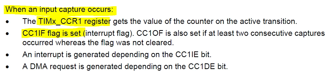
When a capture occurs, the corresponding CCXIF flag (TIMx_SR register) is set and an interrupt or a DMA request can be sent if they are enabled. If a capture occurs while the CCxIF flag was already high, then the over-capture flag CCxOF (TIMx_SR register) is set. CCxIF can be cleared by software by writing it to ‘0’ or by reading the captured data stored in the TIMx_CCRx register. CCxOF is cleared when written with ‘0’.

 In theory, I could check cyclically against that flag inside the register and decide whether captures are availabe or not?!?

Is that correct or is it an errata in the manual ?

TDK
January 27, 2022

CCRx registers are updated when there is an event. So if you remove the source, no event, they are not updated or changed. You can use the CCxIF flags to know when they have been updated.

Best way to handle IC events IMO is to let the timer free-run and calculate difference in counts between events.

The overflow flag is independent of IC events.

"If you feel a post has answered your question, please click ""Accept as Solution""."
Floki.1
Floki.1Author
Associate II
January 27, 2022

Hello TDK,

thanks for your answer.

What is your assumption in your explaination? Interrupt enabled or not ? In my case, I would like to not use any interrupt overhead for PWM input measurement as I can easily read CCR1 for the period and CCR2 for the width.

So the statement written in the manual as well as your statement that the CCxIF flag is just set after each consecutive successful input capture is still valid? Or do I need to enable interrupt ?

TDK
TDKBest answer
January 27, 2022

I made no assumptions about interrupts being enabled or not. CCxIF is set even if CCxIE isn't set.

0693W00000JNcDoQAL.png

"If you feel a post has answered your question, please click ""Accept as Solution""."
Paul1
Senior III
January 28, 2022
Error while parsing Rich Text Content
Paul1
Senior III
January 28, 2022

1) To handle a fast PWM with high resolution and minimal CPU overhead the Advanced timer is the answer. You could finagle things but why not do this method? Better to mod a prototype board and have circuit best for production.

2) For slower PWMs there are several possibilities, but it really depends on the frequencies and resolution compared to SysClk. A combination of a free running timer with an interrupt, or a system counter, and GPIO interrupts on each iPWM that trigger reading the timer/counter upon each edge (No edges detected in periodic interrupt by clearing the saved counter value after processing)

3) I suggest looking at MOOCS, H7 GPTIM, and

- C:\Users\xxxx\STM32Cube\Repository\STM32Cube_FW_H7_V1.9.0\Projects\NUCLEO-H743ZI\Examples\TIM\TIM_InputCapture

- I put the links for these and more but this forum ate them :(

Paul

Floki.1
Floki.1Author
Associate II
January 28, 2022

Hello,

@TDK​ 

thanks for the feedback, this is exaactly what I wanted. I tested this approach with minimal SW overhead when taking the flags into account and I am able to reset the frequency parameter to 0 in a simple and determinisitc fashion.

@Community member​ 

yes you are right but my board is taking advantage of all other peripheries provided by the ST platform. Therefore, only few pins are left over for the PWM input capture feature which is in my case just few basic timer as the different interfaces have a much higher priority from user perspective.

mpen.1
Associate II
February 1, 2022

hi ,I m tring to connect or find infos how to connect the pin of the STM32H743 to the stlink for coding?Do you have suggestions?

TDK
February 1, 2022

@mpen.1​ Create a new thread instead of posting on an unrelated one.

Look at "SWJ debug port pins" here:

https://www.st.com/resource/en/application_note/an4938-getting-started-with-stm32h74xig-and-stm32h75xig-hardware-development-stmicroelectronics.pdf

ST boards have a debugger on them already which you can use.

"If you feel a post has answered your question, please click ""Accept as Solution""."
mpen.1
Associate II
February 1, 2022

I know what do you mean! the thing I ve done it already!They didn't replay me yet.Do you thing there s a way to work wireless in the maintime?