

Solved
Probleme on getting clock signal on SPI slave device,
Hi ,
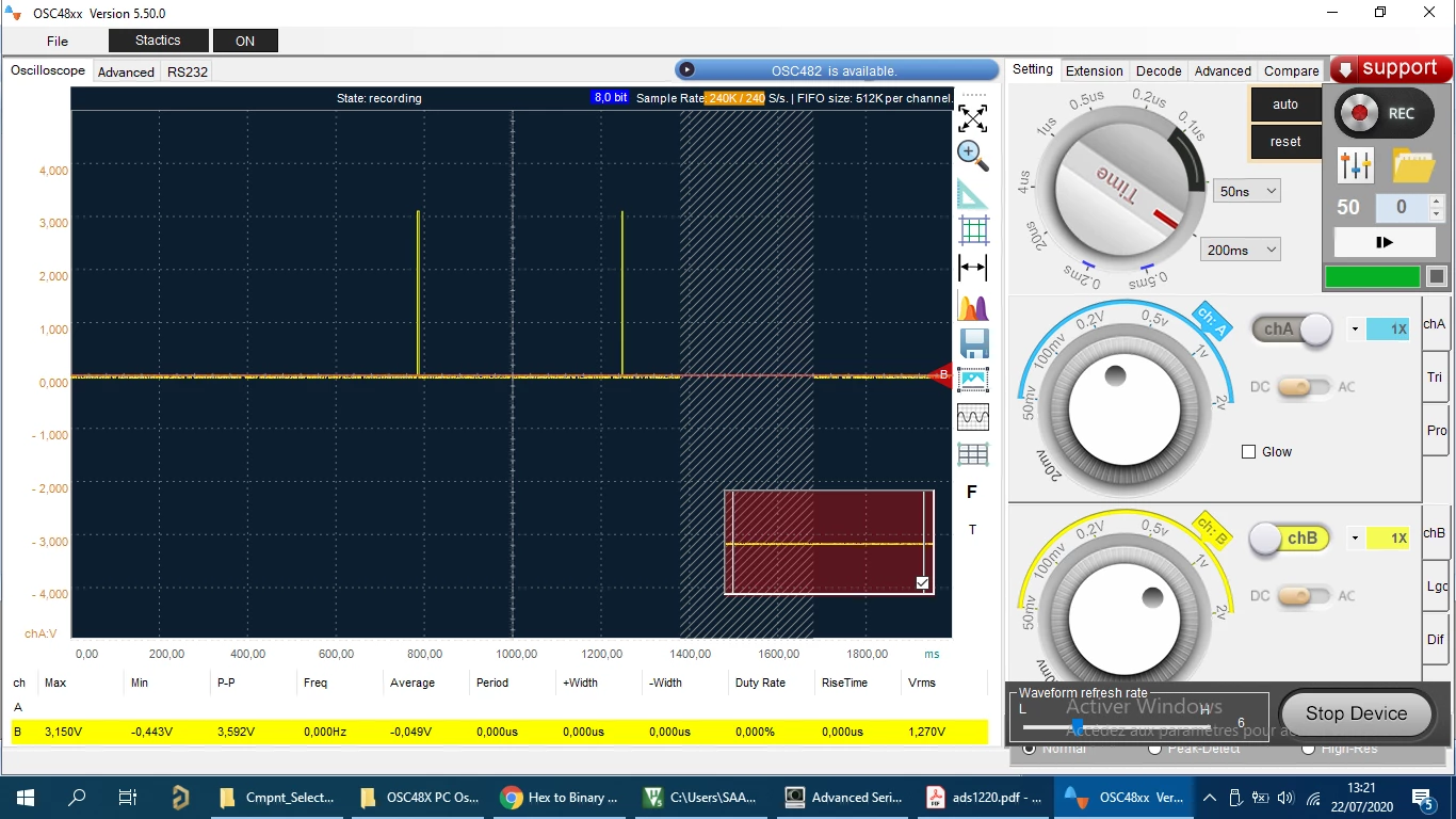
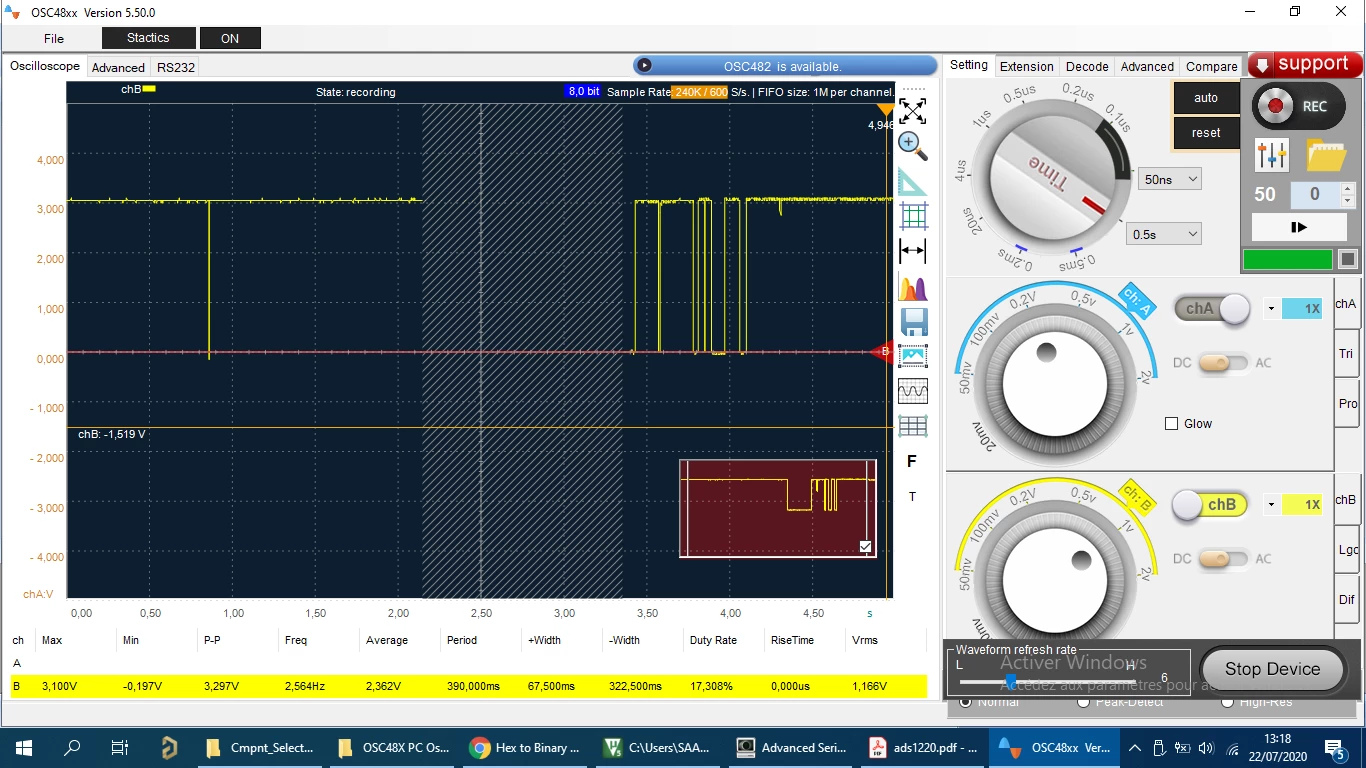
i have a problem with SPI slave device, it doesn't receive the clock signal from stm32f103 (Master), i have configured the baud rate correctly : 72Mhz/32 (SPI1), which is inside the range clock freq of slave device, CS pin is active low so when i send a command i set CS = 1(low), i have checked many parameters but i still have nothing in clk clock, MOSI , MISO line are ok, as shown in these pictures below, please if anyone has any suggestion ! this is the SPI1 config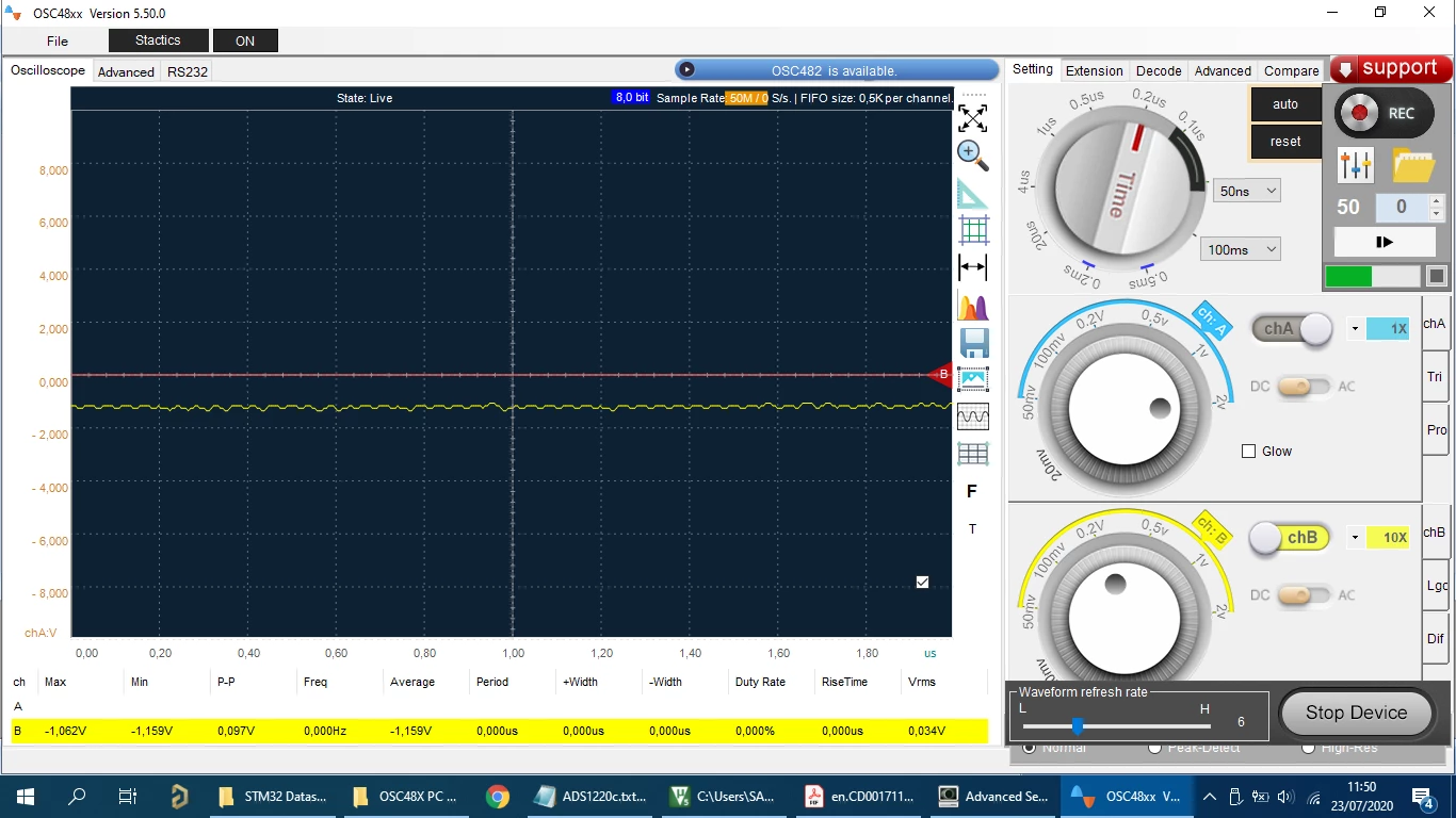
 code
code
void SPI1_init(void){

		//1 : Configure SPI1 GPIO's
		//---------------------------

		// Enable clocks for PORTA, PORTC and SPI1 peripheral
		RCC->APB2ENR |= RCC_APB2ENR_IOPAEN;
		RCC->APB2ENR |= RCC_APB2ENR_IOPCEN;


		// Setup (PA4-->NSS /PA5-->SCK / PA6-->MISO / PA7-->MOSI) as Alternate function for SPI1

		// PA4 --> CS as Output AF push-pull (50Mhz) ref p167-161
	GPIOA->CRL |= GPIO_CRL_MODE4_0 ;
	GPIOA->CRL |= GPIO_CRL_MODE4_1;
	GPIOA->CRL &=~ GPIO_CRL_CNF4_0;
	GPIOA->CRL |= GPIO_CRL_CNF4_1;

		// PA5-->SCK as Master AF push-pull
	GPIOA->CRL |= GPIO_CRL_MODE5_0 ;
	GPIOA->CRL |= GPIO_CRL_MODE5_1;
	GPIOA->CRL &=~ GPIO_CRL_CNF5_0;
	GPIOA->CRL |= GPIO_CRL_CNF5_1;

		// PA6-->MISO as Full-Duplex MASTER -->Input pull up
	GPIOA->CRL &=~ GPIO_CRL_MODE6_0 ;
	GPIOA->CRL &=~ GPIO_CRL_MODE6_1;
	GPIOA->CRL &=~ GPIO_CRL_CNF6_0;
	GPIOA->CRL |= GPIO_CRL_CNF6_1;

		// PA7-->MOSI as Full-Duplex MASTER -->AF push-pull
	GPIOA->CRL |= GPIO_CRL_MODE7_0 ;
	GPIOA->CRL |= GPIO_CRL_MODE7_1;
	GPIOA->CRL &=~ GPIO_CRL_CNF7_0;
	GPIOA->CRL |= GPIO_CRL_CNF7_1;

	// Enable SPI1 clock
		RCC->APB2ENR |= RCC_APB2ENR_SPI1EN;

			//2 : Configure SPI1 P707-743
		//---------------------------
	SPI1->CR1 &=~SPI_CR1_BIDIMODE; // Use 2 lines Full duplex
	SPI1->CR1 &=~ SPI_CR1_DFF; // 8 bits Data Frame Format p742
	SPI1->CR1 &=~SPI_CR1_RXONLY ; // set RXONLY to 0 to select Full-Duplex Mode

	SPI1->CR1 &=~SPI_CR1_LSBFIRST;

	//XXXXXXXXXXXXXXXXXXXXXXXXXXXXXXXXXXXXXXXXXXXX
	 SPI1->CR1 &=~SPI_CR1_SSM ; // Disable Software slave and set Hardware slave management p703
	 SPI1->CR1 |= SPI_CR1_SSI ;

	SPI1->CR1 |= SPI_CR1_BR_2 ; // Set BR=32 100 Fpclk=72Mhz/32
	SPI1->CR1 &=~ SPI_CR1_BR_0 | SPI_CR1_BR_1 ;

	//SPI1->CR1 |= SPI_CR1_BR_1 | SPI_CR1_BR_0 ; // Set BR=16 Fpclk=72Mhz/16
	//SPI1->CR1 &=~ SPI_CR1_BR_2 ;

	SPI1->CR1 |= SPI_CR1_MSTR ; // Select Master Mode
	SPI1->CR1 &=~ SPI_CR1_CPOL; // Set clock Plority
	SPI1->CR1 |= SPI_CR1_CPHA; // set Clock Phase
	SPI1->CR2 |= SPI_CR2_SSOE ; //Always Master - SSOE in CR2 set to 1, the SPI port is always the MASTER it can use NSS as an
 //output which will change state when it is sending. see P703
	SPI1->CR1 |= SPI_CR1_SPE ; // Enable SPI1 peripheral
	}


	// External/Internal (XTal) clock 8Mhz to run the MCU
	// Clock that the MCU run instructions max 72Mhz -->clock speed
Thank you
