Artem Dmitriev
Associate II
March 1, 2018
Question

Problem with working on 2.5V

  • March 1, 2018
  • 30 replies
  • 6165 views
Posted on March 01, 2018 at 11:10

Hello!

On the PCB from LDO(

MCP1700T-3302E

) 3.3V are supplied 2 chips:

GPS

:

SIM

68

M,

STM32L475RET6.

GPS power supply is controlled by STM.

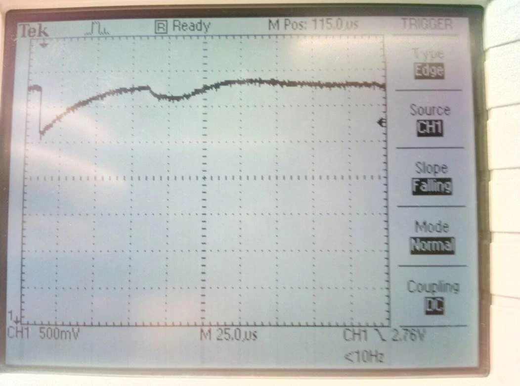
When STM turn on GPS module voltage temporarily drops to 2,5V.

At this time MCU works incorrectly if frequency is 80MHz (hang or HardFault handler are called). If frequency 40Mhz all fine.

What could be the problem?

0690X00000604QlQAI.jpg

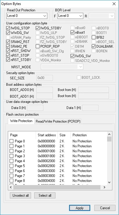
0690X00000604QqQAI.jpg

Note: this post was migrated and contained many threaded conversations, some content may be missing.

    This topic has been closed for replies.

    30 replies

    AvaTar
    Senior III
    March 1, 2018
    Posted on March 01, 2018 at 11:21

    Just guesswork, but:

    When STM turn on GPS module voltage temporarily drops to 2,5V.

    At this time MCU works incorrectly if frequency is 80MHz (hang or HardFault handler are called). If frequency 40Mhz all fine.

    This suggests you have a power supply issue.

    The current consumption of the MCU rises proportional to the core clock frequency.

    I guess either your supply itself is too weak, and falters temporarily under the load, or you need better buffering (larger caps).

    Andrew Neil
    Super User
    March 1, 2018
    Posted on March 01, 2018 at 11:23

    When STM turn on GPS module voltage temporarily drops to 2,5V.

    It is very common that things like GPS draw a considerably higher 'starting' current than 'running' current.

    Your power supply design needs to ensure that your 3.3V rail can cope with this - clearly, it can't!

    You need to fix the 

    power supply design.

    A complex system that works is invariably found to have evolved from a simple system that worked.A complex system designed from scratch never works and cannot be patched up to make it work.
    Artem Dmitriev
    Associate II
    March 1, 2018
    Posted on March 01, 2018 at 11:32

    But why STM works incorrectly if it is capable to work from 1.8V?

    Andrew Neil
    Super User
    March 1, 2018
    Posted on March 01, 2018 at 11:39

    You need to study the datasheet carefully - there are limitations when running at lower voltages...

    Have you tried just running the STM32 at a steady 2.5V ... ?

    A complex system that works is invariably found to have evolved from a simple system that worked.A complex system designed from scratch never works and cannot be patched up to make it work.
    aa bb
    Associate
    March 2, 2018
    Posted on March 02, 2018 at 11:29

    How do you enable the power to your GPS module? At startup, GPS drow a lot of current. you could add a slow inrush current with mosfet..

    Andrew Neil
    Super User
    March 2, 2018
    Posted on March 02, 2018 at 12:37

    aa bb wrote:

    At startup,

    GPS draw a lot of current.

    Indeed - see:

    https://community.st.com/0D50X00009XkWxZSAV

    aa bb wrote:

    you could add a slow inrush current with mosfet..

    Butstudy the GPS documentation carefully - it may not like a slow supply rise ...

    A complex system that works is invariably found to have evolved from a simple system that worked.A complex system designed from scratch never works and cannot be patched up to make it work.
    Dvorak.Peter
    Associate II
    March 4, 2018
    Posted on March 04, 2018 at 00:47

    Using a 0.05 ohm switch to connect a discharged 4.7 uF capacitor to your uC supply is asking for trouble.

    Try removing the C29 (

     4.7 uF) 

    capacitor. The module may have additional internal caps.

    The better solution is the R C modification to the VT9 switch mentioned earlier.

    See 

    https://electronics.stackexchange.com/questions/9307/how-to-limit-inrush-current


    Peter

    Artem Dmitriev
    Associate II
    March 6, 2018
    Posted on March 06, 2018 at 07:03

    We tried to solder L475re on nucleo board. On  the board we see the same situation if we connect GPS module.

    Also we tried to connect GPS module to

    32

    L

    476

    GDISCOVERY board. In this case all work fine.

    We added additional capacitor near gate and this helped to improve step response, MCU works. But the questions is why MCU works incorrectly om 2.5V if it must work down to 1.8V?0690X00000604RoQAI.jpg

    AvaTar
    Senior III
    March 6, 2018
    Posted on March 06, 2018 at 07:19

    But the questions is why MCU works incorrectly om 2.5V if it must work down to 1.8V?

    It would have helped if you observed Vcc with a scope in the critical case.

    I'm pretty sure it dropped far below 1.8V for at least 50 microseconds in this case - a so-called brown-out.

    And second, the minimum operating voltage often implies other restrictions (like reduced core clock), you would need to check for the L475 MCU.

    Artem Dmitriev
    Associate II
    March 6, 2018
    Posted on March 06, 2018 at 07:24

    I tried to find info in datasheet, but I don'd understand where this info is located. Didn't find it.

    Artem Dmitriev
    Associate II
    March 6, 2018
    Posted on March 06, 2018 at 09:18

    We don't see any spikes on oscillograph. 

    MCU works from 1.8V with connected GPS module. But GPS working voltages are 2.8 �?´�?¾ 4.3 V.  On voltages up to 2.8V GPS module doesn't work, voltage drop exists, but MCU works fine. If we connect GPS using voltages 2.8 to 3.6 MCU works incorrectly. 

    AvaTar
    Senior III
    March 6, 2018
    Posted on March 06, 2018 at 10:21

    Honestly, I'm no hardware guy, I can only guess.

    There may still be some issues with the power supply or the buffering, either with the MCU or the GPS module.

    MCU works from 1.8V with connected GPS module. But GPS working voltages are 2.8 �?´�?¾ 4.3 V.  On voltages up to 2.8V GPS module doesn't work, voltage drop exists, but MCU works fine. If we connect GPS using voltages 2.8 to 3.6 MCU works incorrectly. 

    Sounds to me like you have two choices.

    Either have separate supplies (1.8V for the MCU, 2.8V .. 4.3V for GPS), wich might require level shifters for interface lines.

    Or you can pick a voltage both units can operate with, i.e. 2.8V .. 3.6V.

    You would need to investigate the power consumption for both cases, guessing you want to run from battery, and optimize for low power.

    At this time MCU works incorrectly if frequency is 80MHz (hang or HardFault handler are called). If frequency 40Mhz all fine.

    BTW, have you really ruled out a software issue ?

    Perhaps a bug, or your Flash interface setup (waitstates ?) for 80MHz is incorrect.

    Dvorak.Peter
    Associate II
    March 6, 2018
    Posted on March 06, 2018 at 13:36

    Replacing your GPS power switch with the following device will reduce your power supply disturbance and solve all your problems

    The TI TPS2051B power-distribution switches are 

    intended for applications where heavy capacitive

    loads and short circuits are likely to be encountered.

    These devices incorporates 70-mΩ N-channel

    MOSFET power switches for power-distribution

    systems that require multiple power switches in a

    single package. Each switch is controlled by a logic

    enable input. Gate drive is provided by an internal

    charge pump designed to control the power-switch

    rise times and fall times to minimize current surges

    during switching. The charge pump requires no

    external components and allows operation from

    supplies as low as 2.7 V.