

RShre.2
Associate III
June 8, 2023
Question

Problem with timer interrupt

  • June 8, 2023
  • 7 replies
  • 3162 views

I am using HAL_TIM_PeriodElapsedCallback(TIM_HandleTypeDef *htim) to generate a sine wave based on DDS and I have also implemented ADC to get the value and perform some calculation. My sampling rate is 100KHz so my timer interrupt should trigger every 10us.

void HAL_TIM_PeriodElapsedCallback(TIM_HandleTypeDef *htim)

{

HAL_GPIO_WritePin(GPIOA, GPIO_PIN_6, GPIO_PIN_SET);

.................

few codes calling dac and adc

HAL_GPIO_WritePin(GPIOA, GPIO_PIN_6, GPIO_PIN_RESET);

}

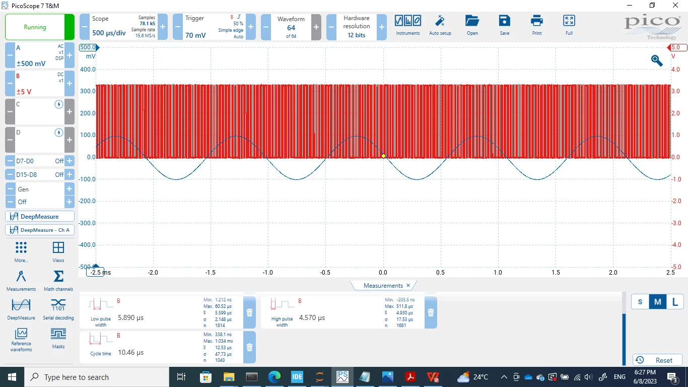
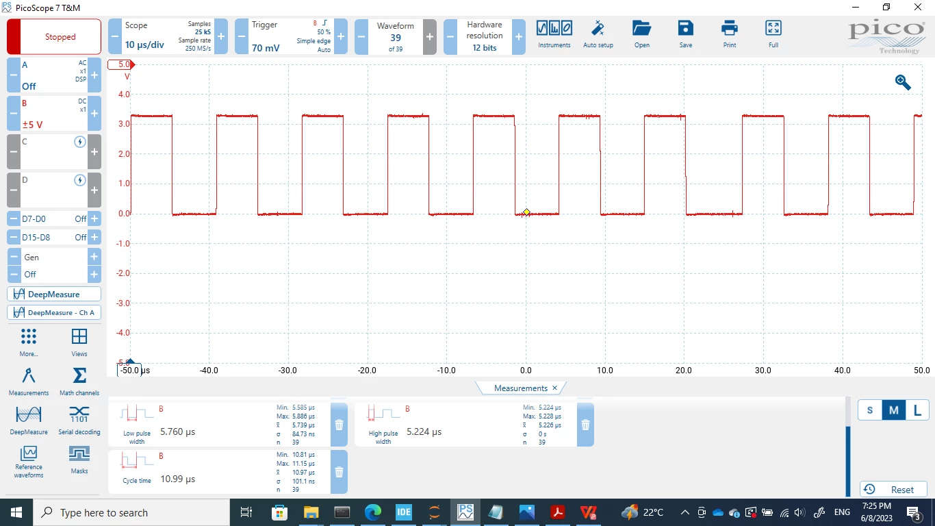
so the execution time is around 4.8us which means the callback function should wait till it reaches 10us and new trigger start if I understand it correctly.

But is it possible that the cycle time for one session exceeds 10us?

The high pulse width is fine, increases with increase in lines of code, but the low pulse width seems to not decrease beyond. This delays my timer interrupt trigger. What is actually happening behind this callback function?

_legacyfs_online_stmicro_images_0693W00000dDQK4QAO.png
_legacyfs_online_stmicro_images_0693W00000dDQKYQA4.png

This topic has been closed for replies.

7 replies

Tesla DeLorean
Guru
June 8, 2023

What's the TIM setting for PSC / ARR ? Remember these are N-1 values, ie last value before wrapping to zero.

Using ST's HAL with it's circuitous routing and call backs can add overhead of it's own.

Consider using DMA to feed pattern buffer values into ARR or CCRx registers at UPDATE

Tips, Buy me a coffee, or three.. PayPal Venmo (See Profile) Up vote any posts that you find helpful, it shows what's working..
RShre.2
RShre.2Author
Associate III
June 12, 2023

i didn't understanding regarding using DMA to feed pattern but I just read a bit about overhead. Maybe I can try accessing the timer directly through registers first and see if that makes any difference. If not, i will try your method. I will get back with an update.

waclawek.jan
Super User
June 8, 2023

> What is actually happening behind this callback function?

Cube is open source, you can/should literally read it to find out what is happening, or also single-step if you want.

JW

Tinnagit
Senior II
June 9, 2023

the timer period is not update, Is this your problem?

I think that you can use timer in PWM mode and update a Pulse value by your ADC value.

it should work.


_legacyfs_online_stmicro_images_0693W00000dDTLZQA4.png
_legacyfs_online_stmicro_images_0693W00000dDTLeQAO.png

S.Ma
Principal
June 9, 2023

While we don't know which STM32 it is, and how the sinewave is generated, I would use Timer to generate the sample frequency for the DAC output generation (timer output pwm trigger signal to wire to the DAC trigger input pin), the DAC is DMA sweeping a waveform cyclically (the sine wave)

Then, if you want to make an ADC measurement, to make it simple, use the same timer PWM and feed it to the ADC trigger pin, which will feed a DMA cyclic buffer for you to sweep.

Tinnagit
Senior II
June 10, 2023

I think that the frequency synchronization between DAC generation and ADC Sampling is not necessary.

You have to sampling ADC at lease double frequency of media signal frequency and you 'll got the necessary data from signal already.

so you can make PWM from it at any frequency you want after it.