TSa.1
Associate
June 11, 2020
Solved

Problem reading gpio pins in parallel from multiple eeproms.
  • June 11, 2020
  • 13 replies
  • 5395 views

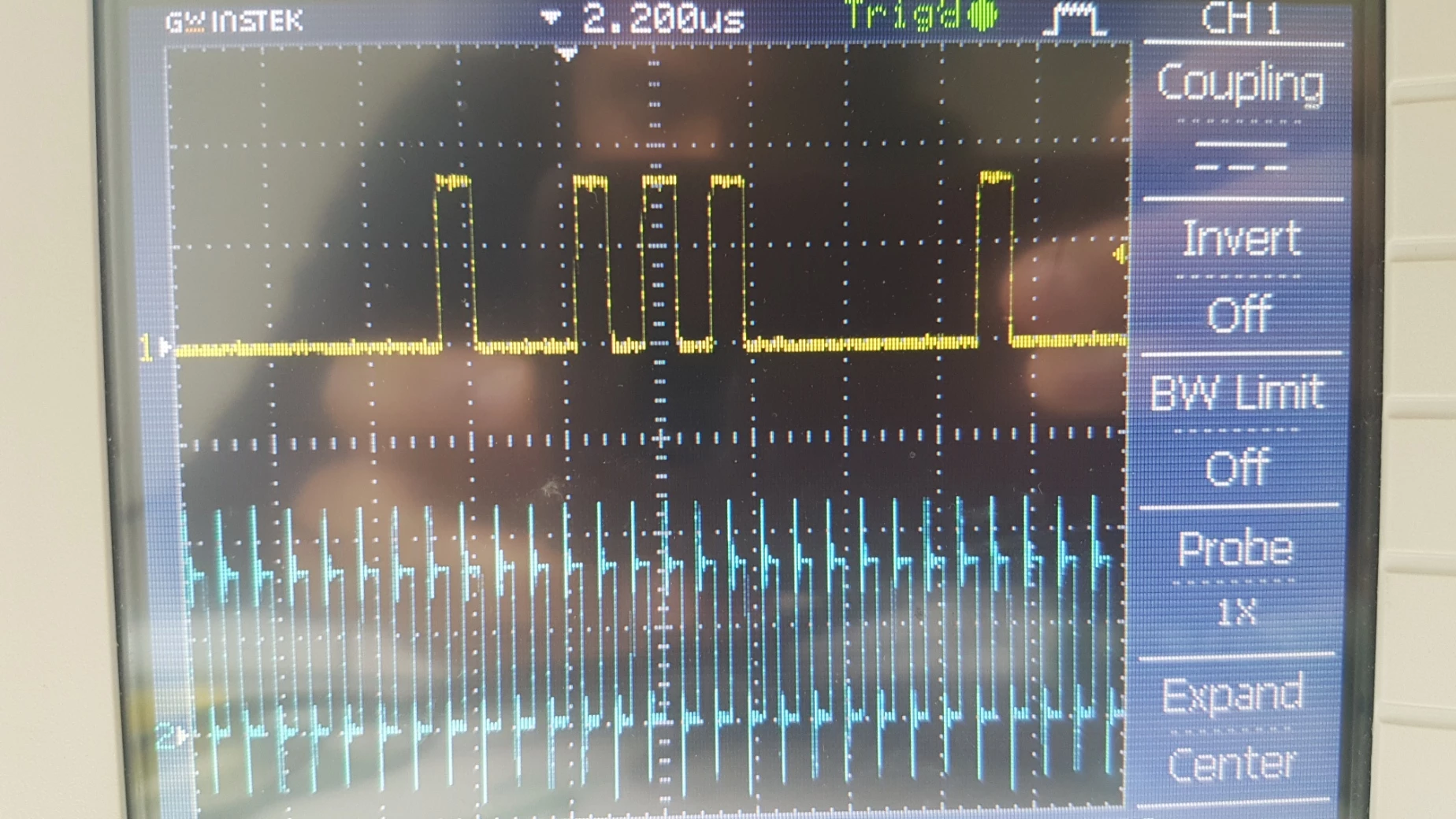
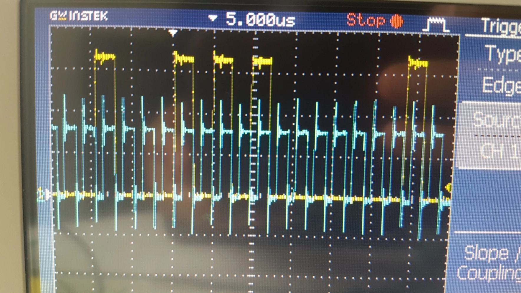
0693W000001qVfmQAE.jpgIm trying to write to and read data from 10 eeproms in parallel. I first transmit the data in parallel to all the eeproms via spi, I then read data in parallel by first transmitting the address of data stored in the eeprom and then transmitting dummy data in non blocking mode in order to pass a clock signal to eeprom and allow it to output data stored.

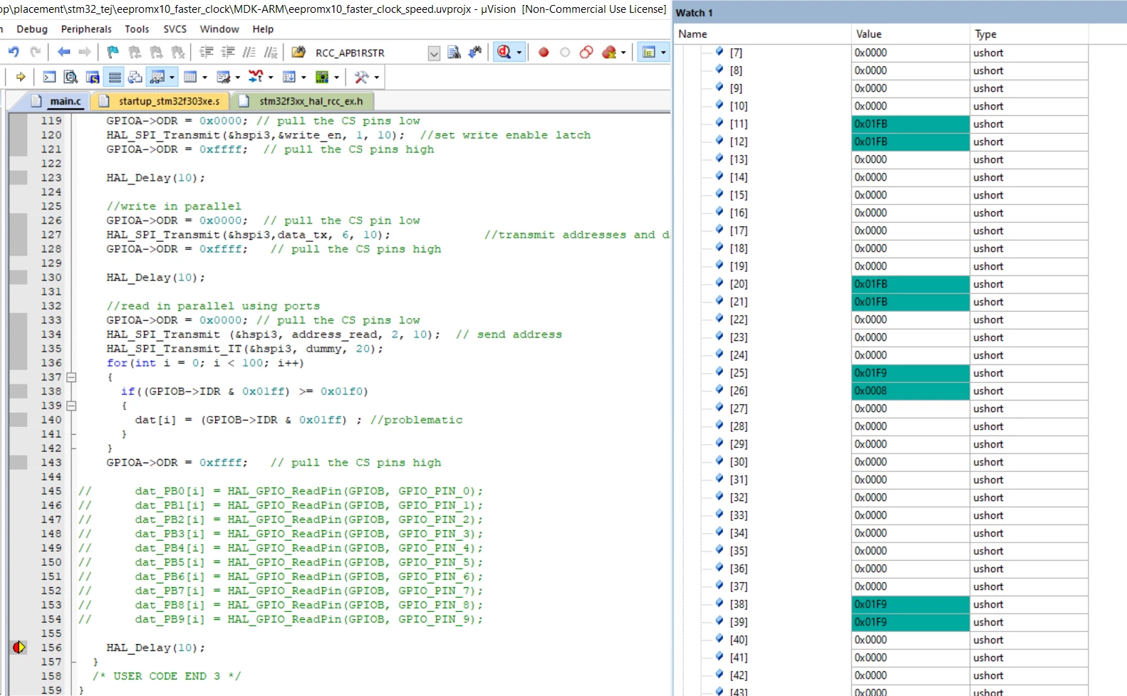
From the signals on my oscilloscope everything works perfectly, the eeprom outputs data I send it. However when trying to read the gpio pins in order to record data only the first 4 bits in every byte gets read as observed from debug mode.

Attached is my code and relevant pics.

Thanks for your help.

Edit: Solution in last post
0693W000001qVKyQAM.jpg0693W000001qVKjQAM.png

uint8_t data_tx[6]={2,0,0,1,21,1}; //0,1,5,1 is data i send to store
uint8_t address_read[4]={3,0};
uint8_t write_en=6;
uint16_t dat[100];
uint8_t dummy[3]={0,0,0}; 
 
while (1)
 {
		//set write enable latch in parallel
		GPIOA->ODR = 0x0000; // pull the CS pins low
		HAL_SPI_Transmit(&hspi3,&write_en, 1, 10);	//set write enable latch
		GPIOA->ODR = 0xffff; // pull the CS pins high
		
		HAL_Delay(10);
		
		//write in parallel
		GPIOA->ODR = 0x0000; // pull the CS pin low
		HAL_SPI_Transmit(&hspi3,data_tx, 6, 10);						 //transmit addresses and data
		GPIOA->ODR = 0xffff; // pull the CS pins high
		
		HAL_Delay(10);
		
		//read in parallel using ports
		GPIOA->ODR = 0x0000; // pull the CS pins low
		HAL_SPI_Transmit (&hspi3, address_read, 2, 10); // send address
		HAL_SPI_Transmit_IT(&hspi3, dummy, 20);
		for(int i = 0; i < 100; i++) 
		{	
			if((GPIOB->IDR & 0x01ff) >= 0x01f0) 
			{
				dat[i] = (GPIOB->IDR & 0x01ff) ; //problematic
			}
		}
		GPIOA->ODR = 0xffff; // pull the CS pins high
		HAL_Delay(10);
 }

This topic has been closed for replies.
Best answer by TSa.1
while (1)
 {
 /* USER CODE END WHILE */
		HAL_GPIO_DeInit(GPIOC, GPIO_PIN_10);
		MX_SPI3_Init();	
 
		//set write enable latch in parallel
		GPIOA->ODR = 0x0000; // pull the CS pins low
		HAL_SPI_Transmit(&hspi3,&write_en, 1, 1);	//set write enable latch
		GPIOA->ODR = 0xffff; // pull the CS pins high
		
		HAL_Delay(10);
		
		//write in parallel
		GPIOA->ODR = 0x0000; // pull the CS pin low
		HAL_SPI_Transmit(&hspi3,data_tx, 6, 6);						 //transmit addresses and data
		GPIOA->ODR = 0xffff; // pull the CS pins high
		
		HAL_Delay(10);
		
		//read in parallel using ports
		GPIOA->ODR = 0x0000; // pull the CS pins low
		HAL_SPI_Transmit(&hspi3, address_read, 2, 2); // send address
		
		HAL_SPI_DeInit(&hspi3); //deinitialise spi
		
		HAL_GPIO_WritePin(GPIOC, GPIO_PIN_10, GPIO_PIN_RESET); //make sck a gpio
		GPIO_InitTypeDef GPIO_InitStruct = {0};
		GPIO_InitStruct.Pin = GPIO_PIN_10;
		GPIO_InitStruct.Mode = GPIO_MODE_OUTPUT_PP;
		GPIO_InitStruct.Pull = GPIO_NOPULL;
		GPIO_InitStruct.Speed = GPIO_SPEED_FREQ_HIGH;
		HAL_GPIO_Init(GPIOC, &GPIO_InitStruct);
	
		for(int i = 0; i < 25; i++) 
		{	
			HAL_GPIO_WritePin(GPIOC, GPIO_PIN_10, GPIO_PIN_SET);
			if((GPIOC->ODR & 0x0400) == 0x0400) 
			{
				dat[i] = ((GPIOB->IDR) & 0x03ff);
			}
			HAL_GPIO_WritePin(GPIOC, GPIO_PIN_10, GPIO_PIN_RESET);
		}
		GPIOA->ODR = 0xffff; // pull the CS pins high
		
		HAL_Delay(10);
 /* USER CODE BEGIN 3 */
 }

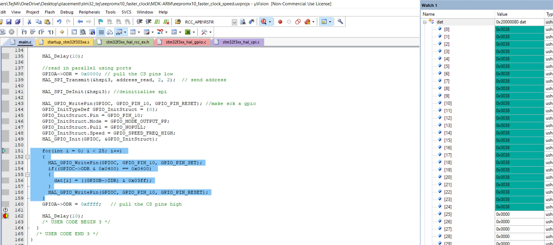
So it works now, I get a correct output on the oscilloscope. However, I dont think im sampling data GPIO correctly:

I transmit 3 bytes: 1,21,1 but this is what I see in debug mode:

What do u think is the issue?

0693W000001qXkeQAE.png

0693W000001qXmuQAE.jpg

13 replies

waclawek.jan
Super User
June 11, 2020

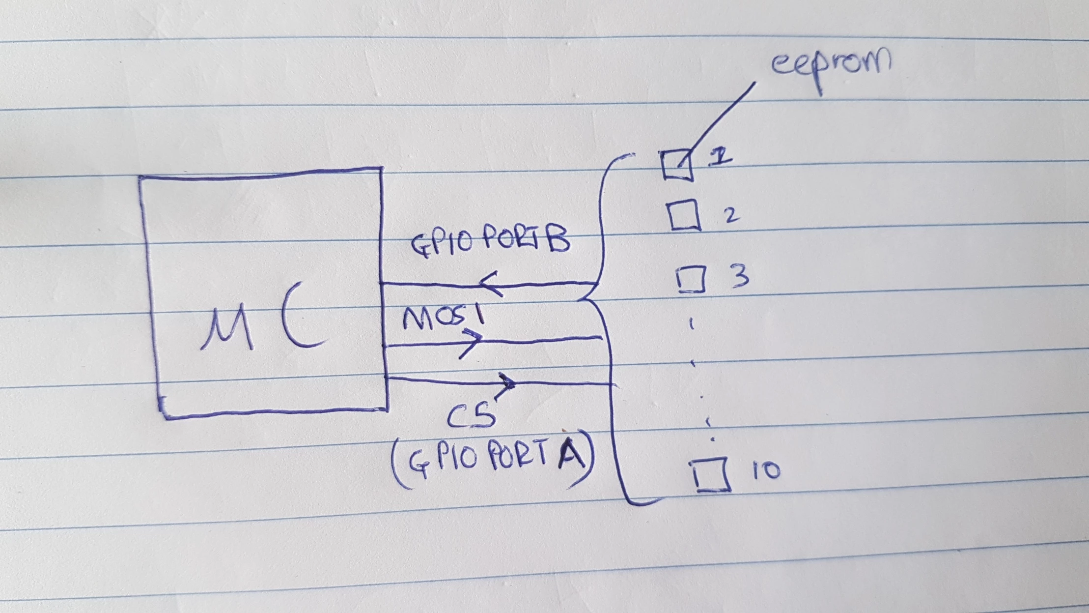
Maybe a diagram or sketch of the hardware connection would help us understand, what are you trying to accomplish.

JW

TDK
June 11, 2020

Not sure I follow what your code is trying to do.

This loop doesn't send any clock output. Why would the IDR value change from loop to loop?

		for(int i = 0; i < 100; i++) 
		{	
			if((GPIOB->IDR & 0x01ff) >= 0x01f0) 
			{
				dat[i] = (GPIOB->IDR & 0x01ff) ; //problematic
			}
		}

"If you feel a post has answered your question, please click ""Accept as Solution""."
TSa.1
TSa.1Author
Associate
June 11, 2020

Tnx for answering TDK

Well HAL_SPI_Transmit_IT(&hspi3, dummy, 20); transmits dummy data (just 0), so essentially it only passes a clock to the eeproms. Since the previous line of code HAL_SPI_Transmit (&hspi3, address_read, 2, 10); requests eeprom to send data from the particular access as soon as it receives the clock it begins outputting data. Each eeprom outputs darta to its respective gpio pin

TSa.1
TSa.1Author
Associate
June 11, 2020

Tnx for answering,I hope this block dig helps waclawek.jan0693W000001qVfmQAE.jpg

TDK
June 11, 2020

Instead of calling HAL_SPI_Transmit_IT, you should be toggling SCK manually and then reading GPIOB on each cycle. You have no delays in your loop and no method to ensure each call is at the right time with respect to the SCK line state.

"If you feel a post has answered your question, please click ""Accept as Solution""."
TSa.1
TSa.1Author
Associate
June 11, 2020

Thats a good suggestion, I wasnt able to find out how to toggle sck manually. How do you go about this?

TDK
June 11, 2020
Reconfigure it as gpio and toggle as needed.
"If you feel a post has answered your question, please click ""Accept as Solution""."
TSa.1
TSa.1Author
Associate
June 11, 2020

Alright, i'll give that a shot! Thannk you for your help

waclawek.jan
Super User
June 11, 2020

> it doesn't seem to work

What are the symptoms?

Did you observe the pins (SCK and some of the MISO/PBx)?

JW

TSa.1
TSa.1AuthorBest answer
Associate
June 11, 2020
while (1)
 {
 /* USER CODE END WHILE */
		HAL_GPIO_DeInit(GPIOC, GPIO_PIN_10);
		MX_SPI3_Init();	
 
		//set write enable latch in parallel
		GPIOA->ODR = 0x0000; // pull the CS pins low
		HAL_SPI_Transmit(&hspi3,&write_en, 1, 1);	//set write enable latch
		GPIOA->ODR = 0xffff; // pull the CS pins high
		
		HAL_Delay(10);
		
		//write in parallel
		GPIOA->ODR = 0x0000; // pull the CS pin low
		HAL_SPI_Transmit(&hspi3,data_tx, 6, 6);						 //transmit addresses and data
		GPIOA->ODR = 0xffff; // pull the CS pins high
		
		HAL_Delay(10);
		
		//read in parallel using ports
		GPIOA->ODR = 0x0000; // pull the CS pins low
		HAL_SPI_Transmit(&hspi3, address_read, 2, 2); // send address
		
		HAL_SPI_DeInit(&hspi3); //deinitialise spi
		
		HAL_GPIO_WritePin(GPIOC, GPIO_PIN_10, GPIO_PIN_RESET); //make sck a gpio
		GPIO_InitTypeDef GPIO_InitStruct = {0};
		GPIO_InitStruct.Pin = GPIO_PIN_10;
		GPIO_InitStruct.Mode = GPIO_MODE_OUTPUT_PP;
		GPIO_InitStruct.Pull = GPIO_NOPULL;
		GPIO_InitStruct.Speed = GPIO_SPEED_FREQ_HIGH;
		HAL_GPIO_Init(GPIOC, &GPIO_InitStruct);
	
		for(int i = 0; i < 25; i++) 
		{	
			HAL_GPIO_WritePin(GPIOC, GPIO_PIN_10, GPIO_PIN_SET);
			if((GPIOC->ODR & 0x0400) == 0x0400) 
			{
				dat[i] = ((GPIOB->IDR) & 0x03ff);
			}
			HAL_GPIO_WritePin(GPIOC, GPIO_PIN_10, GPIO_PIN_RESET);
		}
		GPIOA->ODR = 0xffff; // pull the CS pins high
		
		HAL_Delay(10);
 /* USER CODE BEGIN 3 */
 }

So it works now, I get a correct output on the oscilloscope. However, I dont think im sampling data GPIO correctly:

I transmit 3 bytes: 1,21,1 but this is what I see in debug mode:

What do u think is the issue?

0693W000001qXkeQAE.png

0693W000001qXmuQAE.jpg

TSa.1
TSa.1Author
Associate
June 11, 2020

Nevermind, this works now! I dont know why it started working all of a sudden